









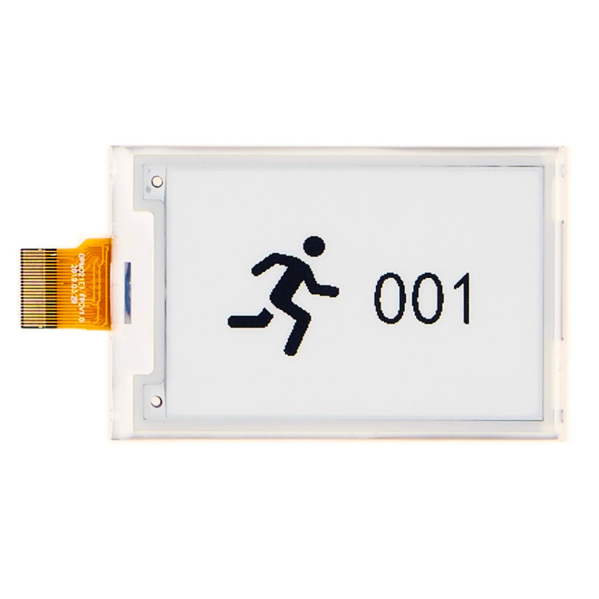
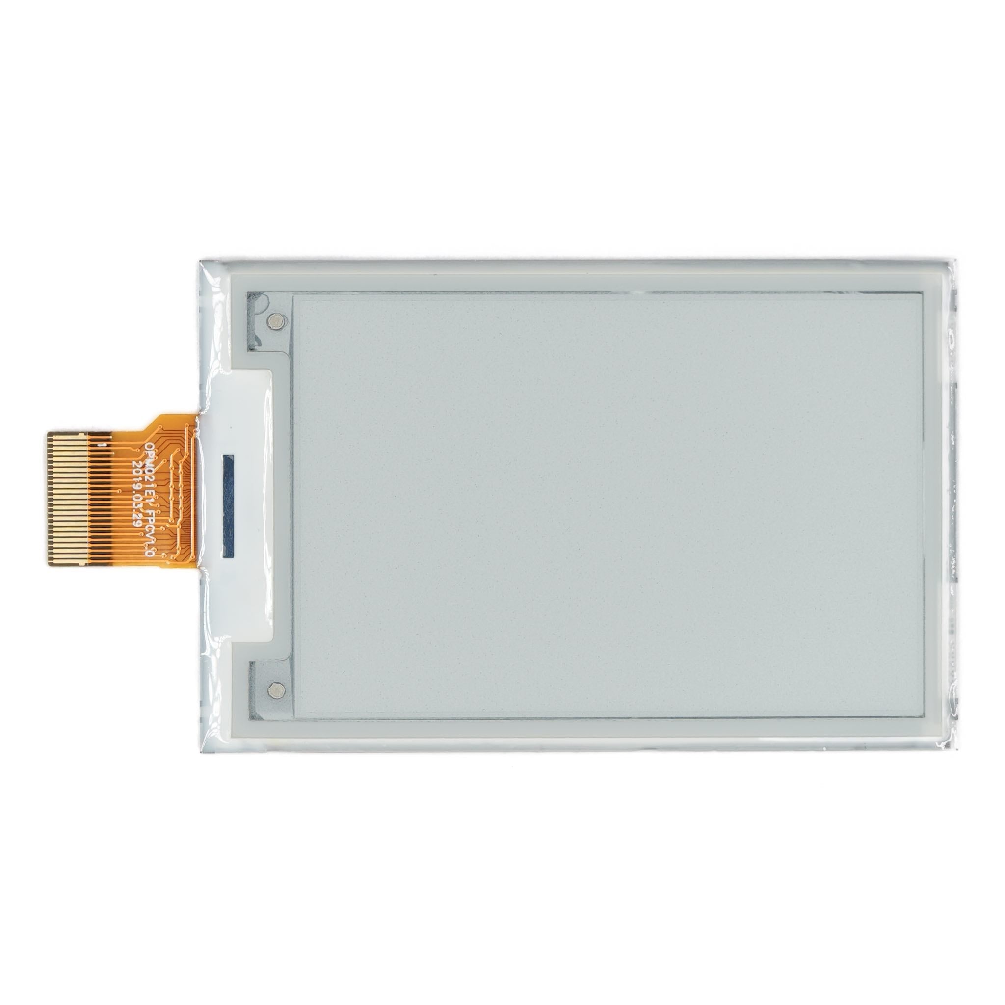
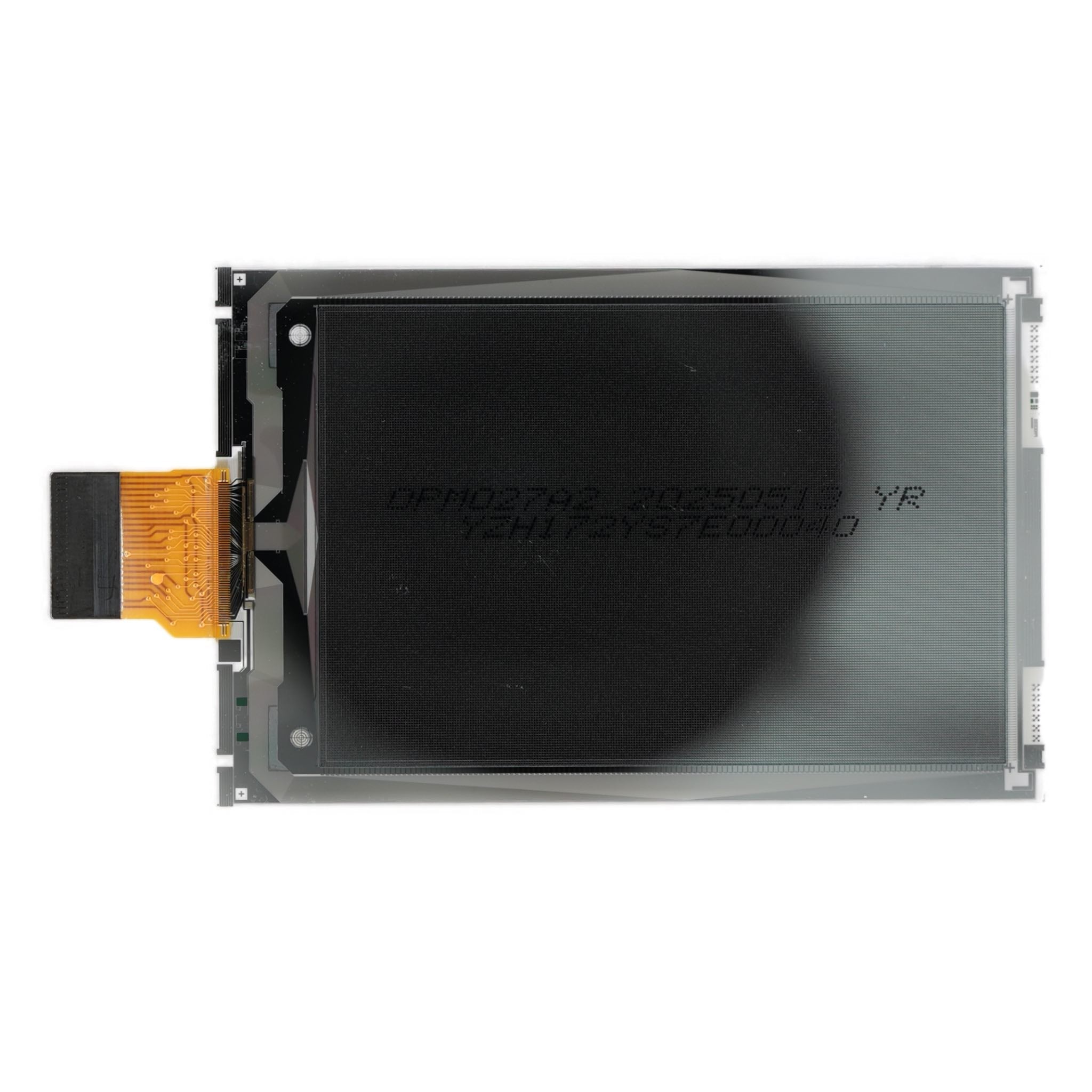
2.7" ePaper Display 176×264 - SPI I2C
- 💹 Enjoy a 20% discount for orders over 500
- 📉 A 15% discount is available for orders ranging from 200 to 499
- 🎁 A 10% discount is available for orders ranging from 50 to 199
- 🎁 A 5% discount is available when ordering 10-49
Interested in customizing this product? Get in touch with us.
Order samples, immediate delivery.
Factory bulk lead time: 3 weeks.
2.7" ePaper Display 176×264 - SPI I2C
- 💹 Enjoy a 20% discount for orders over 500
- 📉 A 15% discount is available for orders ranging from 200 to 499
- 🎁 A 10% discount is available for orders ranging from 50 to 199
- 🎁 A 5% discount is available when ordering 10-49
Resources & Downloads
2.7-Inch 176×264 ePaper Display with SPI
DMAYE02701INA is a 2.7-inch active matrix electrophoretic display with a 176×264 pixel array. The module combines a TFT-driven EPD panel with an integrated MCU interface, timing control, oscillator, DC-DC converter, display RAM, waveform LUT, VCOM circuit, and gate/source drive functions.
The display supports selectable 4-wire SPI and 3-wire 9-bit SPI for command and image-data transfer. Separate TSCL and TSDA signals provide an I2C master interface for communication with an external digital temperature sensor.
Reference document: Product Specification DMAYE02701INA, Version V1.0.0, dated July 1, 2025. Refer to the latest approved datasheet and mechanical drawing before product integration.

Product Features
The following panel and controller functions are listed in the DMAYE02701INA product specification.
Reflective Display
Pure reflective operation with 45% minimum white reflectivity and a 20:1 minimum contrast ratio.
Bi-Stable Image
The panel is specified as a bi-stable display.
Integrated Functions
On-chip display RAM, OTP waveform storage, oscillator, booster, regulator control, and display-driving circuits.
Flexible Orientation
The product specification lists both landscape and portrait display modes.
Technical Specifications
The values below are taken from Product Specification DMAYE02701INA, Version V1.0.0.
| Parameter | Specification |
|---|---|
| Product SKU | DMAYE02701INA |
| Display Technology | Active Matrix Electrophoretic Display (AM EPD) |
| Screen Size | 2.7 inches |
| Resolution | 176(H)×264(V) pixels |
| Pixel Configuration | Rectangular |
| Pixel Pitch | 0.217×0.217 mm |
| Active Area | 38.192×57.288 mm |
| Outline Dimensions | 45.8(H)×70.42(V)×0.82(D) mm |
| Display Mode | Pure reflective, bi-stable |
| Display Orientation | Landscape and portrait |
| Display Interface | 4-wire SPI or 3-wire 9-bit SPI |
| Serial Operation | Write-only in SPI mode |
| Temperature Sensor Interface | I2C master interface for an external digital temperature sensor |
| Logic Supply Voltage | 2.2 V minimum, 3.0 V typical, 3.6 V maximum |
| Typical Operating Current | 4.0 mA typical, 15 mA maximum at VDD = 3.0 V and 25°C |
| Sleep Current | 20 µA with RAM retained |
| Deep-Sleep Current | 1 µA with RAM not retained |
| Deep-Sleep Power | 3 µW |
| Operating Temperature | 0°C to 50°C |
| Operating Relative Humidity | Up to 70% RH |
| Operating Illuminance | Indoor operation, up to 2000 lux |
| Weight | TBD in the supplied product specification |
| RoHS | Marked as compliant in the supplied product specification |
SPI and Temperature-Sensor Interface
The BS pin selects the display-data interface. TSCL and TSDA are assigned to an external digital temperature sensor and are not specified for image-data transfer.
Bus Selection
BS low selects 4-wire SPI. BS high selects 3-wire 9-bit SPI. Both serial modes support write operations only.
4-Wire SPI
SCL functions as SCLK, SDA functions as SDIN, CSB is the active-low chip-select input, and D/C selects command or display data.
3-Wire 9-Bit SPI
SCL functions as SCLK and SDA as SDIN. Each transfer contains one D/C bit followed by data bits D7-D0.
BUSYN
When BUSYN is high, do not interrupt the controller operation or send commands.
External Temperature Sensor
TSCL and TSDA provide clock and bidirectional data signals for an external digital temperature sensor.
Optical Performance and Refresh Time
Optical measurements use 45-degree illumination with perpendicular detection. Refresh values apply with the waveform provided for this panel.
Optical test note: White reflectivity was measured with an Eye-One Pro spectrophotometer. Contrast ratio is defined as all-white surface reflectance divided by all-black surface reflectance.
Mechanical Integration
Use the mechanical drawing to confirm the module outline, active area, FPC location, contact direction, pin-1 position, component clearances, and enclosure window.
Pin Functions
The 24-pin FPC combines host-interface signals, power pins, external temperature-sensor signals, and display-driving nodes.
Host Interface and Control
- BS: Selects 4-wire SPI or 3-wire 9-bit SPI.
- BUSYN: Busy-state output.
- RSTN: Active-low reset input.
- D/C: Data/command selection in 4-wire SPI mode.
- CSB: Active-low chip-select input.
- SCL / SDA: SPI clock and serial data input.
Temperature-Sensor Signals
- TSCL: I2C clock output to an external digital temperature sensor.
- TSDA: Bidirectional I2C data for an external digital temperature sensor.
Power and Core Pins
- VDD: Power for the interface logic and integrated chip.
- VSS: Ground.
- VDDD: Core logic power pin; the datasheet requires a capacitor between VDDD and VSS.
- VPP: OTP programming supply.
Display-Driving and Control Nodes
- GDR / RESE: MOSFET gate-drive control and current-sense input.
- VDHR / VSH: Positive source-driving voltages.
- VGH / VGL: Positive and negative gate-driving voltages.
- VSL: Negative source-driving voltage.
- VCOM: VCOM driving voltage.
Integration note: Follow the complete pin assignment and typical application circuit in the datasheet. Keep each NC pin open and do not connect NC pins together.
Power Modes and Logic Levels
The listed current values apply at VDD = 3.0 V and 25°C under the test conditions stated in the product specification.
Logic thresholds: VIH is 0.8×VDD minimum and VIL is 0.2×VDD maximum. The -0.5 V to +4.0 V logic-supply value is an absolute maximum rating, not the normal operating range.
Reliability Test Conditions
The product specification lists the following operating, storage, environmental, and shipment-package test conditions.
High-temperature operation: +50°C, 30% RH, 240 hours.
Low-temperature operation: 0°C, 240 hours.
High-temperature storage: +70°C, 23% RH, 240 hours.
Low-temperature storage: -25°C, 240 hours.
High-temperature, high-humidity operation: +40°C, 90% RH, 168 hours.
High-temperature, high-humidity storage: +60°C, 80% RH, 240 hours.
Thermal shock: -25°C for 30 minutes to +70°C for 30 minutes, 100 cycles.
Shipment package vibration: 1.04 G, 10-500 Hz, X/Y/Z, one hour per direction, fully packed.
Shipment package drop: 122 cm onto concrete, fully packed, using the sequence stated in the datasheet.
Non-operating electrostatic test: Machine model, ±250 V, 0 Ω, 200 pF.
Handling and Storage
The EPD panel contains fragile glass and plastic materials with a soft protective film. Handle the module carefully to reduce the risk of cracks, scratches, and moisture damage.
Recommended Storage Environment
Store the module in its original packaging, away from sunlight and condensation, at 15-35°C and 30-60% RH.
Clean with a soft, dry cloth only. Do not use chemicals or apply pressure to the protective film.
Do not bend, twist, drop, stack, or apply pressure to the panel.
Do not connect or disconnect the interface while the panel is operating.
Avoid acid, alkali, and other corrosive gases.
Protect the panel from moisture, frost, dew, and condensation.
Do not disassemble or reassemble the EPD panel.
Avoid prolonged unprotected exposure to high temperature, high humidity, sunlight, or fluorescent light.
Application and Design Review
The product specification lists Electronic Shelf Label (ESL) systems as the application for this module. For integration, review the host interface, power supply, external temperature sensor, enclosure, and operating environment against the latest specification.
Electronic Shelf Label Systems
Reflective bi-stable operation supports static content without continuous image-retention power.
Mechanical: Verify the outline, active area, FPC position, contact side, and enclosure window.
Electrical: Verify VDD, logic thresholds, reset, BUSYN handling, and the official application circuit.
Interface: Select the correct SPI mode and use the waveform provided for this panel.
Optical: Review contrast, reflectivity, full-refresh flicker, and partial-refresh behavior in the final product.
Environmental: Confirm the 0-50°C operating range and the published humidity and illuminance limits.
Compliance: The datasheet marks RoHS; verify any additional project-level requirements separately.
Frequently Asked Questions
Does the display use I2C for image data?
No. Display commands and image data use 4-wire SPI or 3-wire 9-bit SPI. TSCL and TSDA are specified for an external digital temperature sensor.
Can display data be read back through SPI?
No. The product specification states that only write operations are allowed in serial mode.
Is a touch panel included?
No touch-panel or touch-controller specification is provided for DMAYE02701INA.
Is the controller IC part number specified?
The product specification describes the integrated controller and driver functions but does not identify a controller IC part number.
Can a generic ePaper waveform be used?
The datasheet states that the listed electrical and optical characteristics are guaranteed only with the controller and waveform provided for this panel.
Does 3 µW represent total system power?
No. The datasheet defines 3 µW as panel-controller deep-sleep power under the stated test conditions; it does not specify total system power.
Is a mating connector part number provided?
No mating connector part number is stated in the product specification. Confirm connector selection against the FPC dimensions in the latest mechanical drawing.
Which documents should be used for product integration?
Use the latest approved DMAYE02701INA product specification and mechanical drawing, together with the typical application circuit included in the datasheet.
Download Official Datasheet
Review the DMAYE02701INA product specification for the mechanical drawing, pin assignment, electrical limits, serial timing, optical test conditions, reliability tests, block diagram, and typical SPI application circuit.