









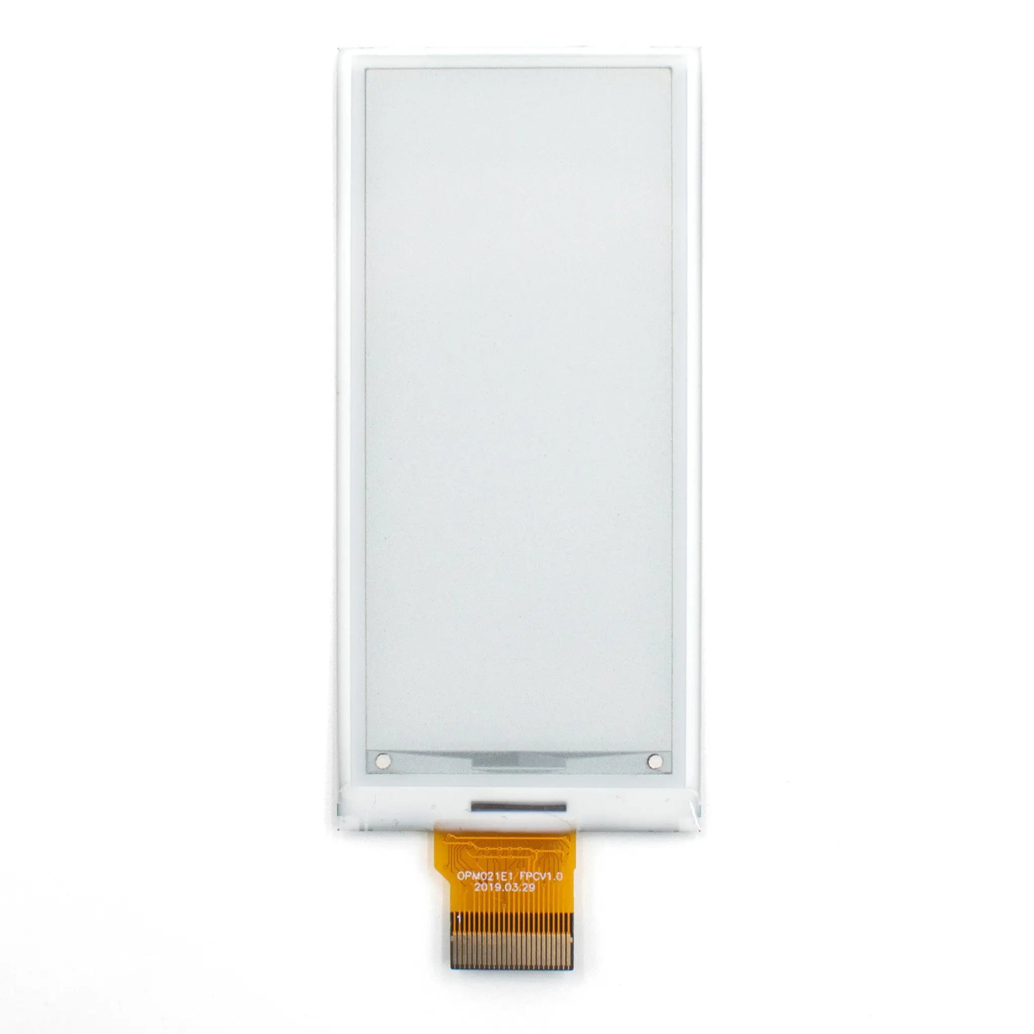
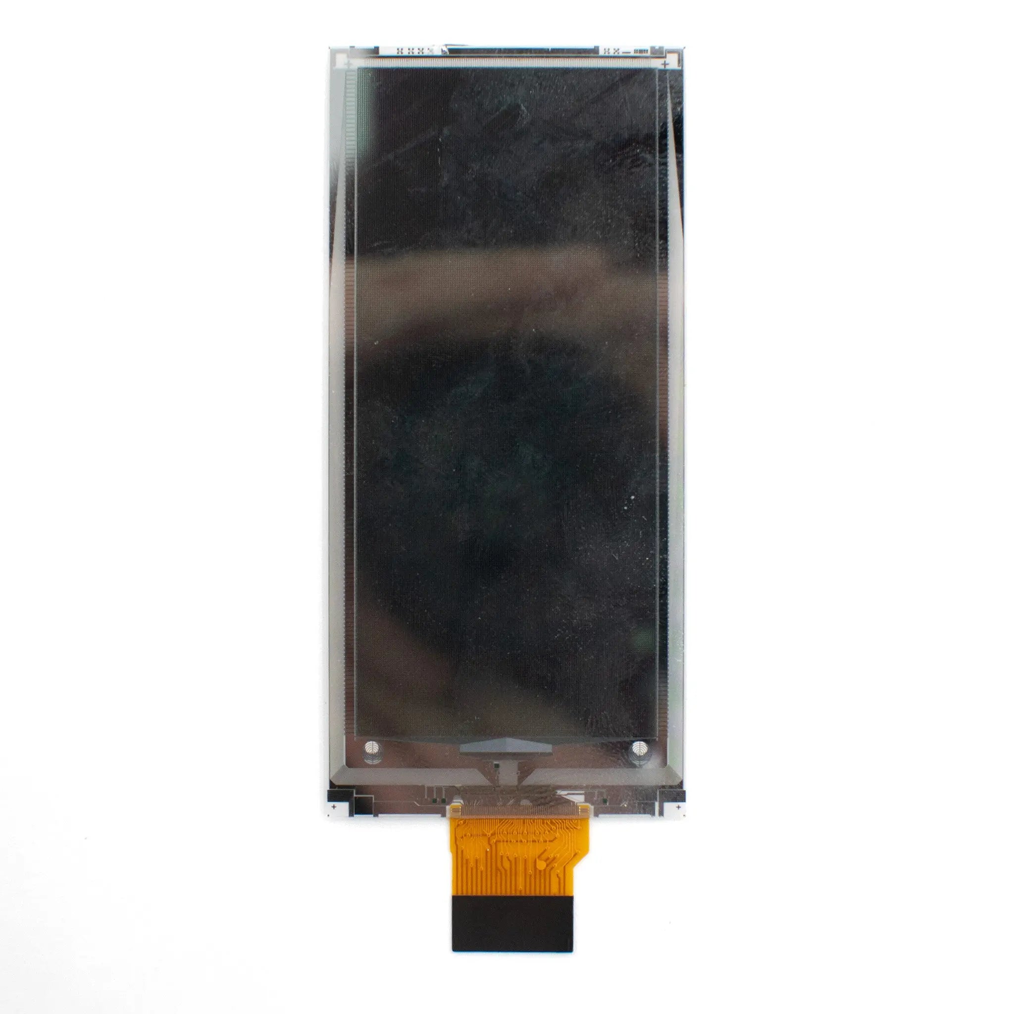
2.9" ePaper 128x296 - IIC/SPI
- 💹 Enjoy a 20% discount for orders over 500
- 📉 A 15% discount is available for orders ranging from 200 to 499
- 🎁 A 10% discount is available for orders ranging from 50 to 199
- 🎁 A 5% discount is available when ordering 10-49
Interested in customizing this product? Get in touch with us.
Order samples, immediate delivery.
Factory bulk lead time: 3 weeks.
2.9" ePaper 128x296 - IIC/SPI
- 💹 Enjoy a 20% discount for orders over 500
- 📉 A 15% discount is available for orders ranging from 200 to 499
- 🎁 A 10% discount is available for orders ranging from 50 to 199
- 🎁 A 5% discount is available when ordering 10-49
Resources & Downloads
2.9-Inch 128×296 Active Matrix ePaper Display
DMAYE0290X5NA is a 2.9-inch active matrix electrophoretic display with a 128×296 pixel matrix, a reflective bi-stable image system, on-chip display RAM, and waveform data stored in OTP. The module is documented for electronic shelf labels and other indoor portable display designs.
Display commands and image data use hardware-selectable 3-wire or 4-wire SPI. The I²C signals are reserved for reading an external digital temperature sensor and are not the display-data interface.
Interface clarification: 4-wire SPI uses a separate D/C signal. 3-wire SPI uses a 9-bit frame containing the D/C bit followed by D7-D0. Both serial display modes are write-only.
Specification basis: DMAYE0290X5NA Product Specification, Version V1.0.0, dated March 8, 2025.

Verified Technical Specifications
The values below are taken from the model-specific product specification. The detailed interface sections of the datasheet are used to distinguish the SPI display interface from the I²C temperature-sensor interface.
| Parameter | Specification |
|---|---|
| Display Size | 2.9 inches |
| Active Area | 29.05 mm (H) × 66.89 mm (V) |
| Resolution | 128 (H) × 296 (V) pixels |
| Pixel Pitch | 227 µm (H) × 226 µm (V) |
| Module Size | 36.70 mm (H) × 79.00 mm (V) × 1.14 mm (D) |
| Weight | 6.9 g |
| Interface | 3-wire or 4-wire SPI for display data; I²C master interface for an external digital temperature sensor |
| Supply Voltage | 2.4 V to 3.6 V; 3.0 V typical |
| Operating Current | 4.0 mA typical at VDD = 3.0 V |
| Sleep Current | 20 µA typical with RAM data retained |
| Deep Sleep Current | 1 µA typical with RAM data not retained |
| White Reflectance | 40% minimum; 43% typical |
| Contrast Ratio | 14:1 minimum; 18:1 typical |
| Full Refresh Time | 600 ms minimum; 1,000 ms typical at 25°C |
| Partial Refresh Time | 300 ms typical at 25°C |
| Operating Temperature | 0°C to +35°C |
| Storage Temperature | -25°C to +60°C |
Optical, Power and Refresh Behavior
The panel is designed around reflective ePaper operation. Static content remains visible without continuous image refresh, while the controller still follows the documented sleep and deep-sleep current values.
Reflective Bi-Stable Display
The panel uses a pure reflective mode and retains the displayed image between updates. It does not require a backlight.
Defined Low-Power States
Sleep mode retains RAM data at 20 µA typical. Deep sleep reduces current to 1 µA typical, but RAM data is not retained.
Full and Partial Refresh
Full refresh may flicker several times. The datasheet states that partial refresh does not flicker during the refresh process.
Waveform-Controlled Performance
The listed optical and electrical characteristics depend on the specified controller and waveform. Use the model-approved waveform stored in OTP.
SPI Interface and Key Signals
The panel supports 3-wire and 4-wire SPI display modes. The BS pin is identified as the hardware bus-interface selection input. The published interface table does not clearly state the required BS logic level for each mode, so confirm the BS connection with DisplayModule before finalizing the PCB.
Write-Only Serial Display Interface
Under both supported SPI modes, only write operations are allowed. Firmware should wait until BUSYN is low before sending commands that could interrupt an active panel operation.
TSCL and TSDA form a separate I²C master interface for an external digital temperature sensor.
4-Wire SPI
Uses SCL as SCLK, SDA as SDIN, CSB as chip select, and a separate D/C input. Data is shifted in as an 8-bit byte from D7 to D0.
3-Wire SPI
Uses SCL, SDA and CSB. Each transfer contains 9 bits: one D/C bit followed by the 8-bit command or display-data byte.
Operating and Reliability Conditions
Use the published environmental limits for product selection, and review the reliability test conditions when assessing the module for the final enclosure and use environment.
Published Use Limits
Operation: 0°C to +35°C
Illuminance: Indoor only, up to 2,000 lux
Storage: -25°C to +60°C
Storage humidity: 30% RH to 60% RH
Temperature operation tests: +35°C at 30% RH for 168 hours and 0°C for 168 hours.
Humidity tests: +40°C at 90% RH during operation and +60°C at 80% RH in storage, each for 168 hours.
Thermal shock: -25°C for 30 minutes to +70°C for 30 minutes, repeated for 100 cycles.
Shipment packaging: Vibration at 1.04 G from 10-500 Hz in X, Y and Z, plus a 122 cm full-package drop sequence.
Non-operating electrostatic test: Machine model ±250 V, 0 Ω, 200 pF, with IEC 62179 and IEC 62180 referenced.
Handling: Protect the glass and plastic structure from bending, twisting, pressure, moisture, condensation and surface scratching.
Integration Notes Before Ordering
Review these points with the final PCB, enclosure and firmware before sample approval or production release.
Mechanical fit: Use the 36.70 × 79.00 × 1.14 mm outline, active area and FPC drawing when designing the enclosure and connector location.
FPC matching: The datasheet shows a 24-pin FPC and pin order but does not name a mating connector. Confirm contact orientation and connector selection with the approved sample.
Peripheral circuit: Follow the reference circuit for GDR, RESE, source and gate voltages, VCOM, capacitors, diodes, MOSFET, resistors and inductor.
Firmware timing: Confirm the required BS connection, follow the published SPI timing, monitor BUSYN, and use the module-specific initialization and waveform sequence.
Environmental fit: Do not assume outdoor use. The published operating condition is indoor only, 0°C to +35°C and up to 2,000 lux.
Compliance review: RoHS is marked in the datasheet. CE, FCC and other certifications are not marked and should not be assumed.
Common Questions Before Ordering
Is I²C used to send image data to the display?
No. Image data and commands use 3-wire or 4-wire SPI. TSCL and TSDA are the I²C master signals for an external digital temperature sensor.
Does the module support both 3-wire and 4-wire SPI?
Yes. The datasheet confirms both modes and identifies BS as the bus-interface selection pin. Because the published interface table does not clearly map BS high or low to each mode, confirm the required BS connection with DisplayModule before finalizing the PCB.
Can the host read display data back through SPI?
No. The datasheet states that only write operations are allowed under the supported serial modes.
Does a static image consume absolutely zero power?
The bi-stable panel retains the image without continuous refresh, but the controller still has documented power states. Deep sleep is specified at 1 µA and 3 µW typical.
Is this panel specified for outdoor use?
No outdoor-use claim is provided. The datasheet specifies indoor operation only, with a maximum operating illuminance of 2,000 lux.
Is a touch panel included?
No touch panel, touch controller or touch-interface specification is listed for DMAYE0290X5NA.
What refresh behavior should firmware expect?
At 25°C, full refresh is 1,000 ms typical and may flicker several times. Partial refresh is 300 ms typical and is described as non-flickering during the refresh process.
Is a rated lifetime published?
No rated lifetime value is stated in the supplied datasheet. Confirm the update frequency, environmental conditions and lifetime target for the final application before ordering.
Download Official Datasheet
Use the official DMAYE0290X5NA datasheet to confirm dimensions, pin definitions, SPI mode selection, electrical limits, optical values, reliability conditions, reference circuitry and integration requirements.
Download Official Datasheet