MCU parallel
IM2/IM1/IM0 select 18-, 9-, 16- or 8-bit MCU operation. Route the data bus and read/write control signals for the selected width.


Popular Products


Interested in customizing this product? Get in touch with us.
Order samples, immediate delivery.
Factory bulk lead time: 3 weeks.
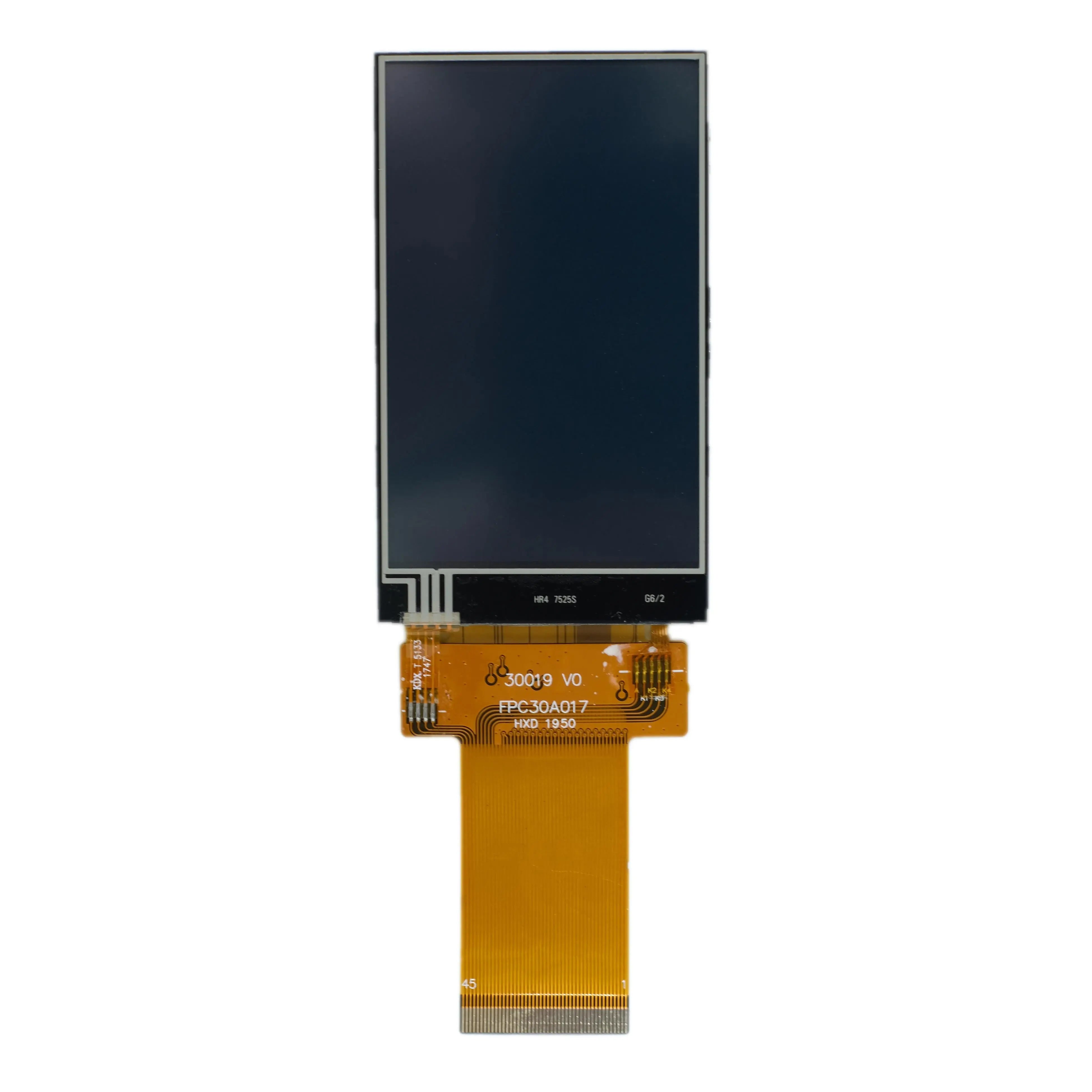
3.0" IPS Display 240x400 Resistive - SPI, MCU, RGB
DM-TFT30-418
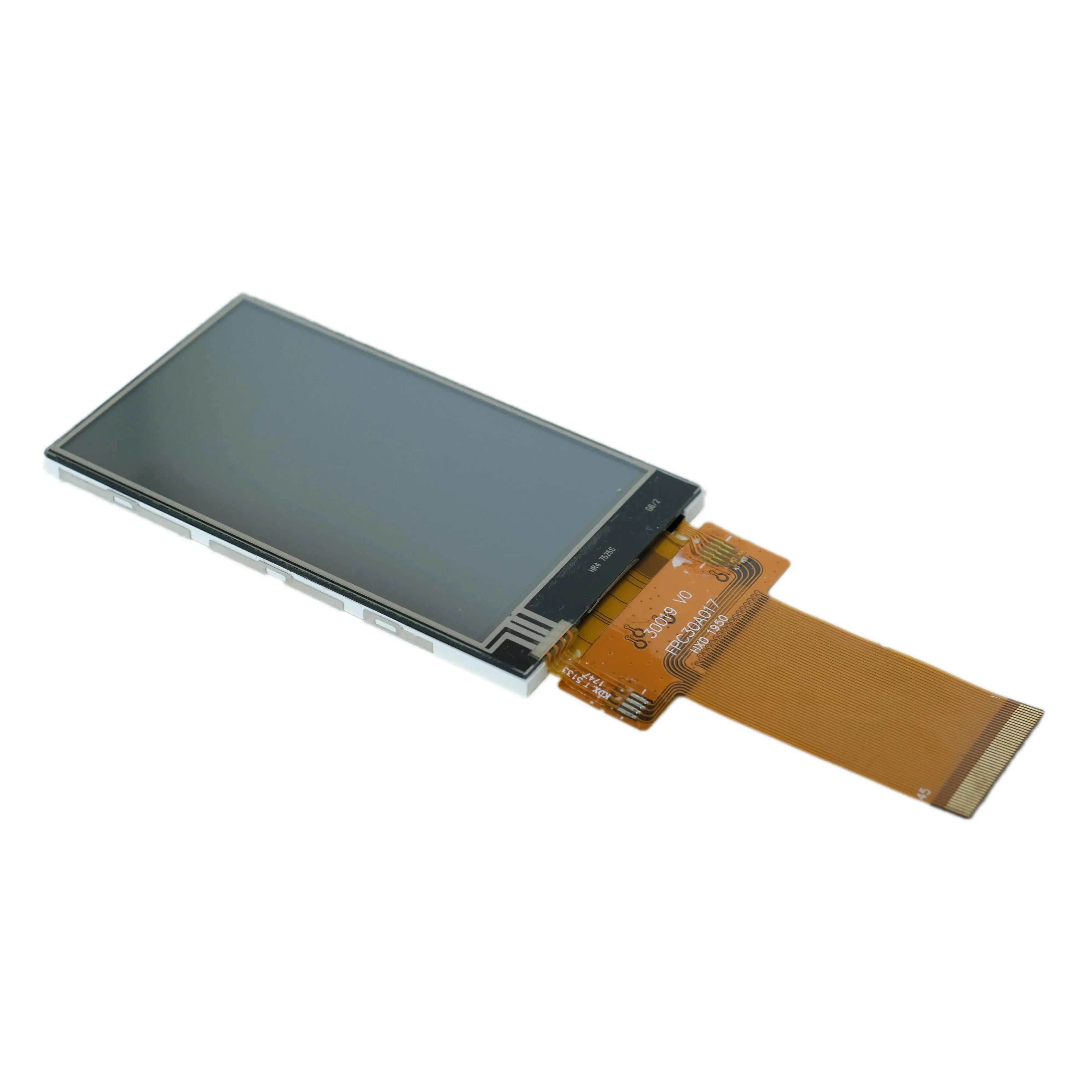
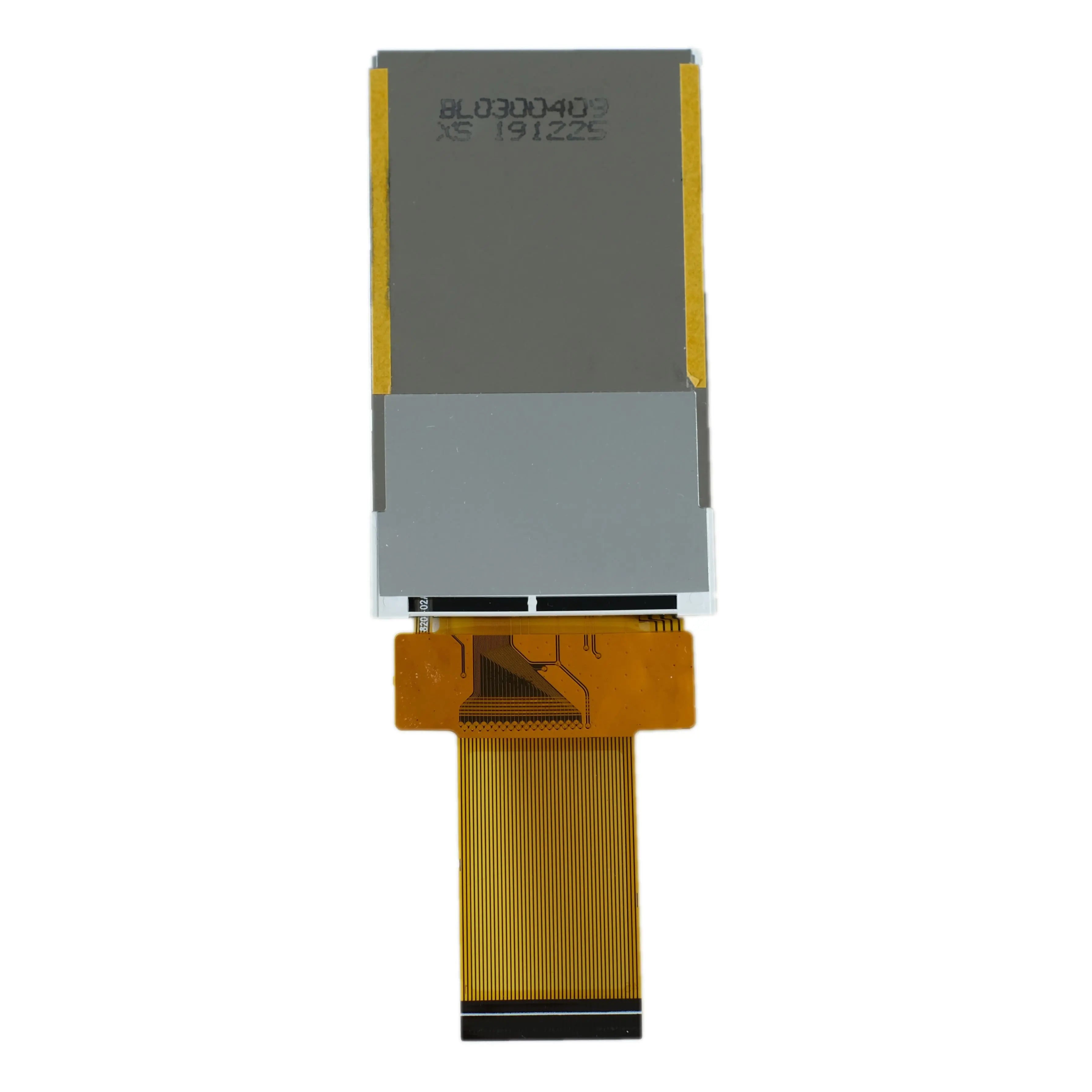
DM-TFT30-418 is a 3.0-inch IPS TFT display with a 240 × 400 portrait matrix and a resistive touch panel. The ILI9327 controller supports MCU, serial and RGB interface options. The 39.24 × 65.4 mm display area is contained in a 45.04 × 77.0 × 3.9 mm module, with display, backlight and four touch terminals on the module connection.
 Click to enlarge
Module outline · schematic view, not to scale
Use the dimensioned engineering drawing to position the cover opening and connection space. The illustration separates the image matrix from the physical module envelope.
Open the DM-TFT30-418 engineering drawing →A tall menu or equipment readout can use the portrait active area with resistive input. Evaluate the chosen touch-reading circuit, target sizes and calibration as part of the complete interface.
Right glass terminal
Left glass terminal
Bottom film terminal
Top film terminal
The four terminals connect the resistive touch layer to the host touch-reading circuit. Coordinate acquisition and calibration are handled by that circuit and its software. The module provides resistive terminals rather than an I²C capacitive touch controller.
The touch specification lists 200–600 Ω for the film-side terminals.
The glass-side terminal resistance is specified at 300–900 Ω.
The touch panel specification lists a maximum voltage of 5 V. This limit applies to the touch layer and does not define the TFT supply voltage.
380 cd/m² typical
8 mA typical
60 mA minimum / 80 mA typical
3.2 V typical
400:1 minimum / 500:1 typical
80° typical, each direction
35 ms typical / 50 ms maximum
−20 to +70 °C
−30 to +80 °C
Keep the display supply, LED drive and touch excitation requirements separate in the schematic. The module pin description specifies a 2.5–3.3 V supply for VCC pins 33–34; consult both the pin assignment and electrical section when choosing the supply rail.
| Parameter | Specification |
|---|---|
| Product model | DM-TFT30-418 |
| Diagonal | 3.0 inch |
| Module dimensions | 45.04 × 77.0 × 3.9 mm |
| Pixel pitch | 0.1635 × 0.1635 mm |
| Display mode | Transmissive; normally black |
| Colors | 65K / 262K |
| Display interface | 8/9/16/18-bit MCU; 3/4-wire SPI + 16/18-bit RGB |
| Viewing direction | All directions |
IM2/IM1/IM0 select 18-, 9-, 16- or 8-bit MCU operation. Route the data bus and read/write control signals for the selected width.
The pin table identifies both 3-wire, 9-bit serial and 4-wire, 8-bit serial modes. WR also serves as the serial clock in DBI Type C mode.
The interface exposes VSYNC, HSYNC, PCLK and DE. Follow the module timing diagrams and ILI9327 register definitions when setting up RGB operation.
The ILI9327 manages the image path. The resistive touch layer exposes four terminals for a host-side reading circuit; that circuit and the application provide coordinate acquisition and calibration.
XR / YD / XL / YU · host reading circuit. Touch acquisition is separate from image transfer.
Provide the specified LED drive independently of the panel logic supply. Include both paths in the power budget.
Functional connection overview for DM-TFT30-418. Use the module pin assignment for the circuit and connector design.
This model exposes four resistive touch terminals: XR, YD, XL and YU. A host-side touch-reading circuit acquires coordinates; no FT-series I²C touch controller is specified for this SKU.
No. The 5 V maximum belongs to the resistive touch layer. The TFT pin description separately specifies VCC pins 33–34 at 2.5–3.3 V.
The touch specification gives film-side resistance of 200–600 Ω and glass-side resistance of 300–900 Ω. The four-terminal pin assignment and these electrical limits are the reference for the host reading circuit.
DisplayModule provides documentation and engineering assistance for display integration. For DM-TFT30-418, include your display bus, four-wire resistive touch-reading circuit and calibration setup when contacting the team.
Use technical support for wiring or documentation questions. Include the model number, connection details and a description of the behavior you observe.
Standard models are available for sample evaluation. For volume orders or proposed modifications, request a quote with your quantity and requirements. Confirm the model-specific MOQ, schedule and customization feasibility with the team.
About DisplayModule · Contact details and service information
Use the DM-TFT30-418 module datasheet for dimensions, connection details and product-specific electrical and optical limits. The controller documents provide the related interface and command reference.