










40x2 Character LCD STN Transflective - MCU
- 💹 Enjoy a 20% discount for orders over 500
- 📉 A 15% discount is available for orders ranging from 200 to 499
- 🎁 A 10% discount is available for orders ranging from 50 to 199
- 🎁 A 5% discount is available when ordering 10-49
Interested in customizing this product? Get in touch with us.
Order samples, immediate delivery.
Factory bulk lead time: 3 weeks.
40x2 Character LCD STN Transflective - MCU
- 💹 Enjoy a 20% discount for orders over 500
- 📉 A 15% discount is available for orders ranging from 200 to 499
- 🎁 A 10% discount is available for orders ranging from 50 to 199
- 🎁 A 5% discount is available when ordering 10-49
Resources & Downloads
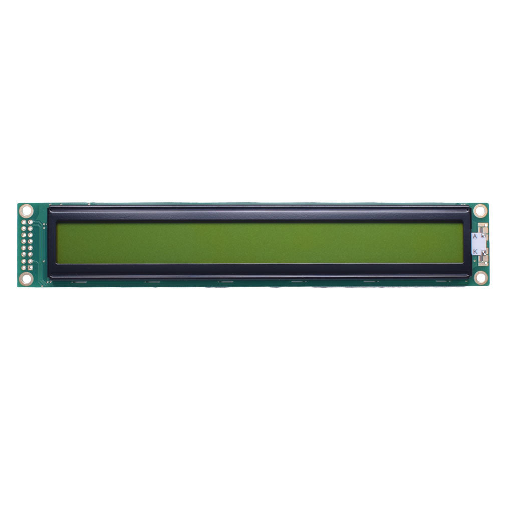
40×2 Character LCD STN Transflective Module with ST7066U Controller
DM-LCD4002-439 is a 40-character by 2-line monochrome LCD module designed for equipment interfaces that require long text fields, status messages, measured values, or operating prompts.
The module uses a yellow-green STN positive transflective display, a yellow-green LED backlight, a 5.0 V supply, and a 6800-series parallel MPU interface. The ST7066U serves as the primary LCD controller and provides display RAM, character-generation resources, cursor functions, display shifting, and 4-bit or 8-bit host communication. A 40×2 implementation may use additional cascaded segment-driver circuitry internally; confirm the exact internal driver configuration before controller-level substitution or schematic reuse.

Technical reference basis: Product data is presented from the DM-LCD4002-439 module specification, mechanical drawing, and Sitronix ST7066U V2.2 controller documentation. Confirm the latest document revision before releasing a production PCB or enclosure.
Documented Technical Specifications
The following values support initial component selection, schematic review, mechanical layout, thermal assessment, and sample qualification.
| Parameter | Documented Specification |
|---|---|
| Product Model | DM-LCD4002-439 |
| Display Format | 40 characters × 2 lines |
| Display Technology | STN positive, yellow-green, transflective |
| Viewing Direction | 6:00 o'clock |
| Module Outline | 182.0 ± 0.5 × 33.5 ± 0.5 × 13.6 mm maximum |
| Viewing Area | 154.4 × 16.65 mm |
| Active Area | 147.5 × 11.15 mm |
| Mounting-Center Spacing | 175.0 mm horizontal and 28.9 mm vertical, according to the mechanical drawing |
| Power Supply | 5.0 V DC nominal |
| Controller IC | Sitronix ST7066U primary LCD controller; a 40×2 implementation may use cascaded segment-driver circuitry internally. Confirm the exact internal driver configuration before controller-level substitution. |
| Host Interface | 6800-series parallel MPU interface |
| Host Data Width | 4-bit or 8-bit transfer supported by the ST7066U controller |
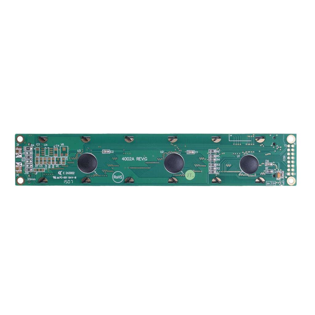
| Interface Footprint | 16-pin through-hole interface footprint, with separate A and K LED backlight terminals shown in the mechanical drawing |
| Backlight | Yellow-green LED |
| Module Supply Current | 1.2 mA typical at 5.0 V; the LED backlight voltage and current are specified separately |
| LED Backlight Voltage | 4.2 V typical |
| LED Backlight Current | 270 mA typical |
| Backlight Luminance | 240 cd/m² typical without the LCD, according to the module specification |
| Contrast Ratio | 3 typical |
| Response Time | 300 ms typical, 400 ms maximum |
| Operating Temperature | -20°C to +70°C |
| Storage Temperature | -30°C to +80°C |
| Module Weight | 85.0 g |
Mechanical Integration Data
The long 182 mm module outline should be reviewed together with the viewing window, active character area, connector clearance, LED backlight depth, and mounting-hole locations.
Module Outline
182.0 × 33.5 × 13.6 mm Max.Allow additional enclosure and PCB clearance for connector access, solder joints, mounting hardware, manufacturing tolerance, and cable routing.
Viewing WindowThe documented viewing area is 154.4 × 16.65 mm. Use this value when defining the enclosure opening and visible border.
Active Character AreaThe active area is 147.5 × 11.15 mm. Keep masks, bezels, and adhesive outside the required visible character region.
Mounting PatternThe mechanical drawing shows 175.0 mm horizontal and 28.9 mm vertical mounting-center spacing. Confirm the PTH and pad diameters directly from the official drawing before enclosure release.
Electrical and Optical Review
Logic power, LCD contrast, and LED backlight power should be treated as separate design considerations. The host board must provide a stable 5.0 V module supply and a backlight drive arrangement suitable for the documented LED operating point.
The module is specified for 5.0 V operation. For the ST7066U at 5.0 V, the documented input-high minimum is 0.7 × VCC, or 3.5 V. Direct control from 3.3 V logic is therefore not guaranteed; use suitable level translation or obtain confirmed module-level input-threshold data before final PCB design.
The module supply-current value is listed separately from the LED backlight rating and does not represent total demand when the backlight is operating.
The backlight is specified at 4.2 V typical and 270 mA typical. Confirm whether external current limiting or a dedicated driver is required in the final circuit.
The luminance value is specified for the backlight without the LCD. Complete-module appearance should be evaluated using a physical sample.
Orient the display and operator sight line according to the documented viewing direction during enclosure and panel design.
The specified response time is 300 ms typical and 400 ms maximum. Evaluate update appearance at the intended operating temperature.
Controller and Host Interface Details
The ST7066U serves as the module's primary LCD controller and provides display memory, character-generation resources, instruction control, cursor functions, and the parallel host interface. In a 40×2 implementation, cascaded segment-driver circuitry may also be used internally.
6800-Series Parallel Interface
The controller supports both 4-bit and 8-bit data transfer. The required control and data signals should be assigned according to the official module pin table.
Power and Contrast: Provide the documented module supply and set the LCD contrast voltage using the final operating environment and viewing-angle requirements.
Control Signals: RS selects the instruction or data register, R/W selects the transfer direction, and E starts the read or write operation.
Data Bus: DB4 through DB7 are used in 4-bit mode. DB0 through DB7 are used in 8-bit mode.
LED Backlight: A and K identify the LED backlight terminals in the drawing. Verify polarity and drive conditions before power is applied.
40×2 DDRAM Address Map
For two-line operation, the ST7066U documentation assigns separate DDRAM address ranges to the two display rows.
The second line does not begin immediately after the final address of the first line. Firmware should use the documented line-start addresses when positioning text.
Firmware Integration Sequence
The controller initialization flow, bus timing, and busy-flag handling should be implemented from the ST7066U V2.2 documentation rather than assumed from another character-LCD module.
Apply Stable Power
Keep supply noise controlled during power rise and ensure the module reaches its required operating voltage before initialization.
Observe Initial Delay
The ST7066U example initialization sequence specifies a wait longer than 40 ms after VCC exceeds 4.5 V before the initial function-set operation.
Select Bus Width
Configure the function-set instruction for the required 4-bit or 8-bit host connection and two-line display operation.
Follow Initialization and Busy-Flag Timing
During power-on initialization, follow the fixed delays in the ST7066U flowcharts and do not read DB7 until the sequence reaches a point where busy-flag checking is permitted. In normal operation, the controller documentation shows a delay greater than 80 µs between an instruction write and the first busy-flag check in the example timing sequences.
Character ROM confirmation: ST7066U variants use different character-generator ROM options. Confirm whether the supplied module uses the English/Japanese or English/European character ROM before ordering for a language-specific project.
Operating and Design Review Points
These checks help engineering and purchasing teams determine whether the module matches the final enclosure, electronics, firmware, environmental range, and production requirements.
Temperature Range
Review the -20°C to +70°C operating range and -30°C to +80°C storage range against the complete product environment.
Interface Pin and PCB Fit
Confirm interface-pin order, footprint orientation, component clearance, soldering access, and the A/K backlight connection before PCB fabrication.
Backlight Driver
Do not size the module power budget from the 1.2 mA module supply-current value alone. Include the documented LED backlight current and driver losses.
Order Configuration
Confirm the required character ROM, backlight appearance, interface configuration, sample availability, lead time, and product revision before volume ordering.
Common Questions Before Sample Evaluation
Is this a graphic LCD?
No. It is a character LCD organized as 40 alphanumeric character positions on each of two lines.
Does the module support a 4-bit interface?
The ST7066U controller supports both 4-bit and 8-bit transfers. Confirm the module pin assignment and firmware timing before completing the host design.
Can it connect directly to a 3.3 V microcontroller?
Direct connection is not guaranteed. At a 5.0 V controller supply, the ST7066U input-high minimum is 0.7 × VCC, or 3.5 V, which is above a nominal 3.3 V logic-high level. Use suitable level translation or obtain confirmed module-level input-threshold data before final PCB design.
How should the backlight current be included in the power budget?
The module specification lists the 1.2 mA supply-current value separately from the LED backlight rating of 4.2 V typical and 270 mA typical. Include both the module supply and the backlight-driver demand when calculating total system power.
What addresses should firmware use for the two lines?
The ST7066U documentation assigns 00H to 27H to the first line and 40H to 67H to the second line in two-line mode.
What should be confirmed before a production order?
Confirm the latest module revision, character ROM option, interface pinout, backlight drive, mechanical drawing, sample performance, availability, and lead time.
Technical Documentation Basis
Use both documents during design review. The module datasheet defines the product-specific dimensions and operating values, while the controller document defines the instruction set, memory addressing, host-bus operation, and initialization requirements.
DM-LCD4002-439 Module Datasheet
Primary reference for the module outline, viewing area, active area, display mode, power data, optical values, temperature limits, backlight information, and mechanical drawing.
ST7066U Controller Datasheet, V2.2
Reference for 4-bit and 8-bit MPU communication, DDRAM addressing, busy-flag operation, instruction functions, character memory, power-on initialization, and interface timing.
Design-control note: Specifications and production configurations can be revised. Use the latest approved datasheet and a representative sample as the final basis for PCB, firmware, enclosure, optical, and purchasing decisions.
Download Official Technical Documentation
Download the official module datasheet to review dimensions, electrical values, optical data, operating limits, backlight requirements, and the mechanical drawing. Use the ST7066U document for controller instructions, timing, addressing, and firmware integration.