









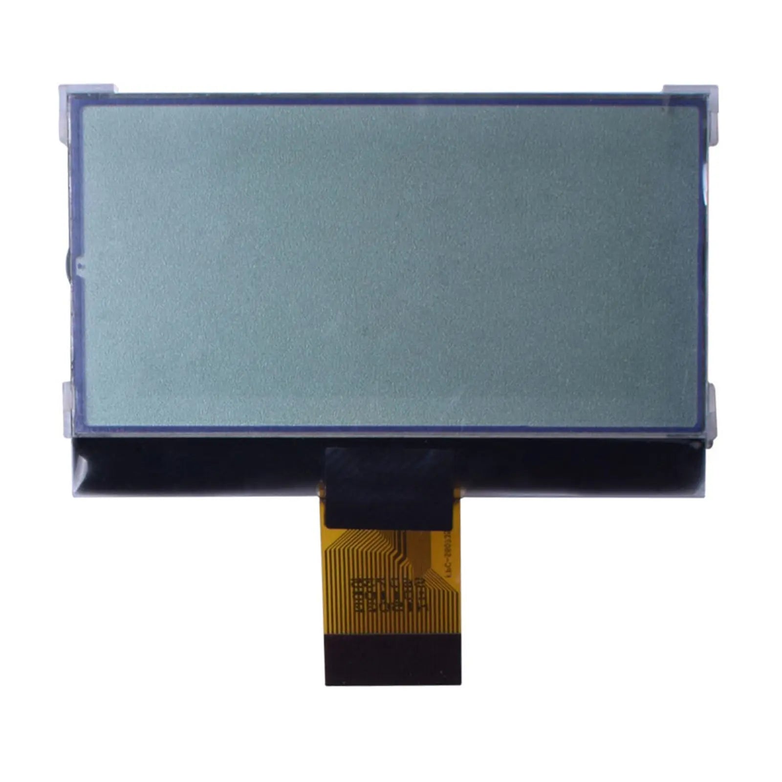
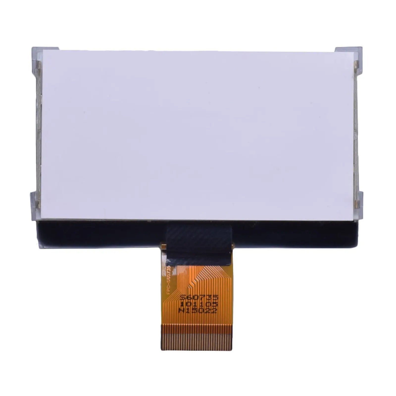
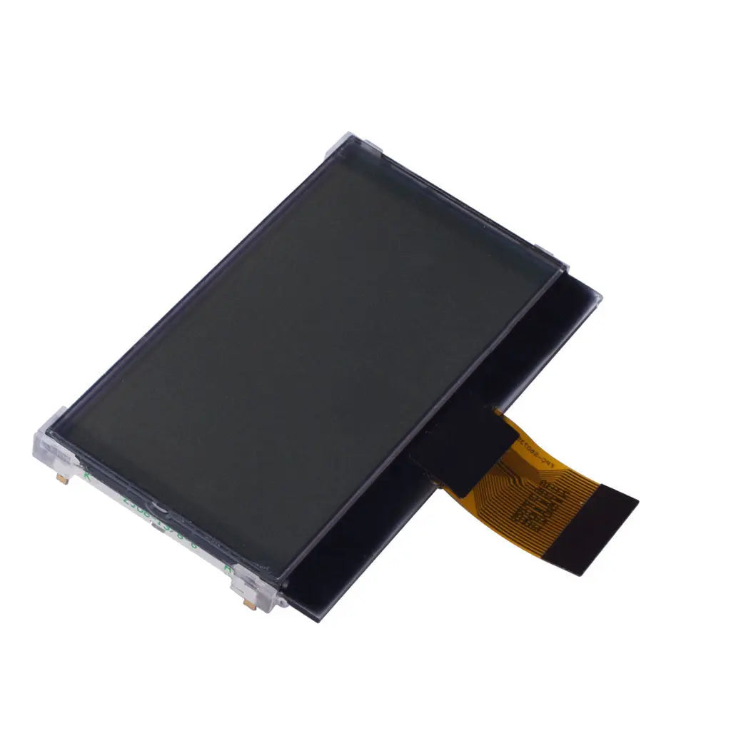
128x64 COG LCD Graphic Display 2.61" - MCU
- 💹 Enjoy a 20% discount for orders over 500
- 📉 A 15% discount is available for orders ranging from 200 to 499
- 🎁 A 10% discount is available for orders ranging from 50 to 199
- 🎁 A 5% discount is available when ordering 10-49
Interested in customizing this product? Get in touch with us.
Order samples, immediate delivery.
Factory bulk lead time: 3 weeks.
128x64 COG LCD Graphic Display 2.61" - MCU
- 💹 Enjoy a 20% discount for orders over 500
- 📉 A 15% discount is available for orders ranging from 200 to 499
- 🎁 A 10% discount is available for orders ranging from 50 to 199
- 🎁 A 5% discount is available when ordering 10-49
Resources & Downloads
128 × 64 COG LCD Graphic Display, 2.61-Inch, ST7565R Controller
DM-COG12864-708 is a 2.61-inch COG graphic LCD module featuring a 128 × 64 pixel FSTN positive transflective display, an ST7565R controller, and a white edge LED backlight.
The module uses a 30-pin, 0.50 mm-pitch FPC and supports 8080 or 6800 MPU interfacing. Its defined active area, viewing area, electrical characteristics, and mechanical drawing provide the information required for MPU interface design, PCB layout, and enclosure integration.
Technical Specifications
Review the key display, interface, electrical, temperature, and mechanical parameters of DM-COG12864-708 for component selection and product integration.
| Parameter | Verified specification |
|---|---|
| Product model | DM-COG12864-708 |
| Nominal display size | 2.61 inch |
| Display construction | COG graphic LCD module |
| Display mode | FSTN, positive, transflective |
| Resolution | 128 × 64 pixels |
| Controller IC | ST7565R |
| MPU interface | 8080 or 6800 MPU interface |
| Drive method | 1/65 duty, 1/9 bias |
| Logic supply | 3.0 to 3.5 V; 3.3 V typical |
| Viewing direction | 12 o'clock |
| Backlight | White edge LED |
| Operating temperature | -20°C to +70°C, absolute maximum |
| Storage temperature | -30°C to +80°C, absolute maximum |
| Module weight | 25.5 g |
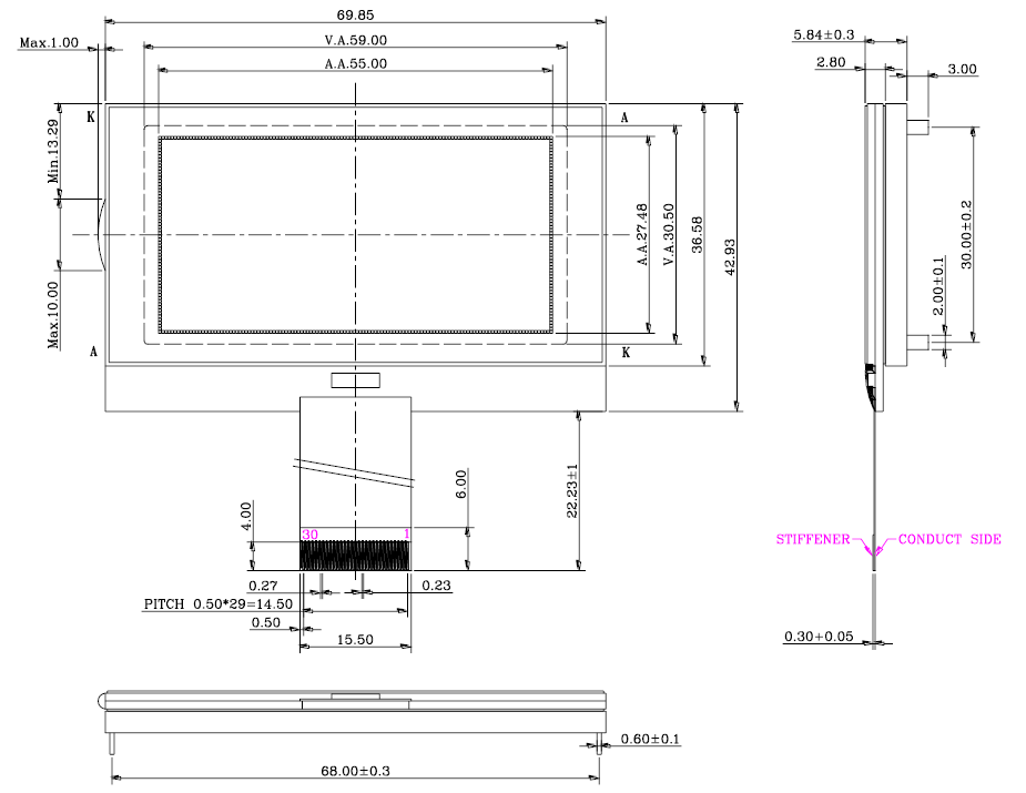
Mechanical Dimensions and FPC Layout
The mechanical drawing defines the LCD outline, viewing area, active area, overall depth, and 30-pin FPC geometry for enclosure, connector, and PCB layout.
LCD glass outline. Use the complete engineering drawing to confirm datum locations, clearances, FPC position, backlight structure, and assembly stack-up.
Electrical and Optical Characteristics
The module operates from a 3.3 V typical logic supply and uses a white LED backlight rated at 6.0 V and 30 mA typical. The datasheet also defines logic levels, operating current, viewing-angle ranges, response time, and contrast ratio.
Electrical Characteristics
Optical Characteristics
30-Pin FPC and MPU Interface
DM-COG12864-708 uses a 30-position FPC with 0.50 mm pitch. The pin assignment includes an 8-bit data bus, control signals, logic power, LCD-drive terminals, and interface-selection pins for 8080 or 6800 MPU operation.
The ST7565 controller documentation also describes serial operation. Confirm the production module configuration before selecting a serial interface for the final design.
For power design, use the assembled module specification of 3.0 to 3.5 V, with 3.3 V typical. The standalone controller document does not override the module-level supply range.
Operating and Reliability Conditions
The documented conditions cover high- and low-temperature storage, powered operation, humidity, thermal shock, vibration, and electrostatic testing. Review them together with the final enclosure, power design, and intended operating environment.
High-Temperature Storage
80°C for 200 hours.
Low-Temperature Storage
-30°C for 200 hours.
Temperature Operation
70°C for 200 hours and -20°C for 200 hours.
Humidity Condition
60°C and 90% RH for 96 hours under no-load conditions, excluding the polarizer.
Thermal Shock
-20°C to +70°C, 10 cycles.
Vibration and Static Electricity
Vibration: 15 mm total fixed amplitude at 10 to 55 Hz, one 60-second cycle, applied in the X, Y, and Z directions for 16 minutes per direction. Static-electricity condition: 800 V with 1.5 kΩ and 100 pF, one application.
Integration Notes
Review the supply, MPU mode, timing, and optical stack before finalizing the PCB, firmware, and enclosure design.
What viewing direction should be used?
The specified viewing direction is 12 o'clock.
Does the module include a touch panel?
The module specification does not identify an integrated touch panel or touch controller. Confirm the required touch configuration before ordering.
Can the module use a serial interface?
The controller documentation describes serial operation, but the module summary specifies 8080 or 6800 MPU interfaces. Confirm the production configuration before using serial mode.
Is a numeric luminance value available?
No numeric luminance value is specified. Check brightness with a sample using the intended backlight drive and optical stack.
What should be checked before ordering samples?
Confirm the drawing revision, FPC orientation, MPU interface, backlight requirements, operating environment, MOQ, and lead time.
Download Technical Documents
Download the module datasheet for mechanical dimensions, pin assignments, electrical limits, optical characteristics, interface timing, reliability conditions, and handling guidance. The ST7565 controller document provides command definitions and controller-function details.