









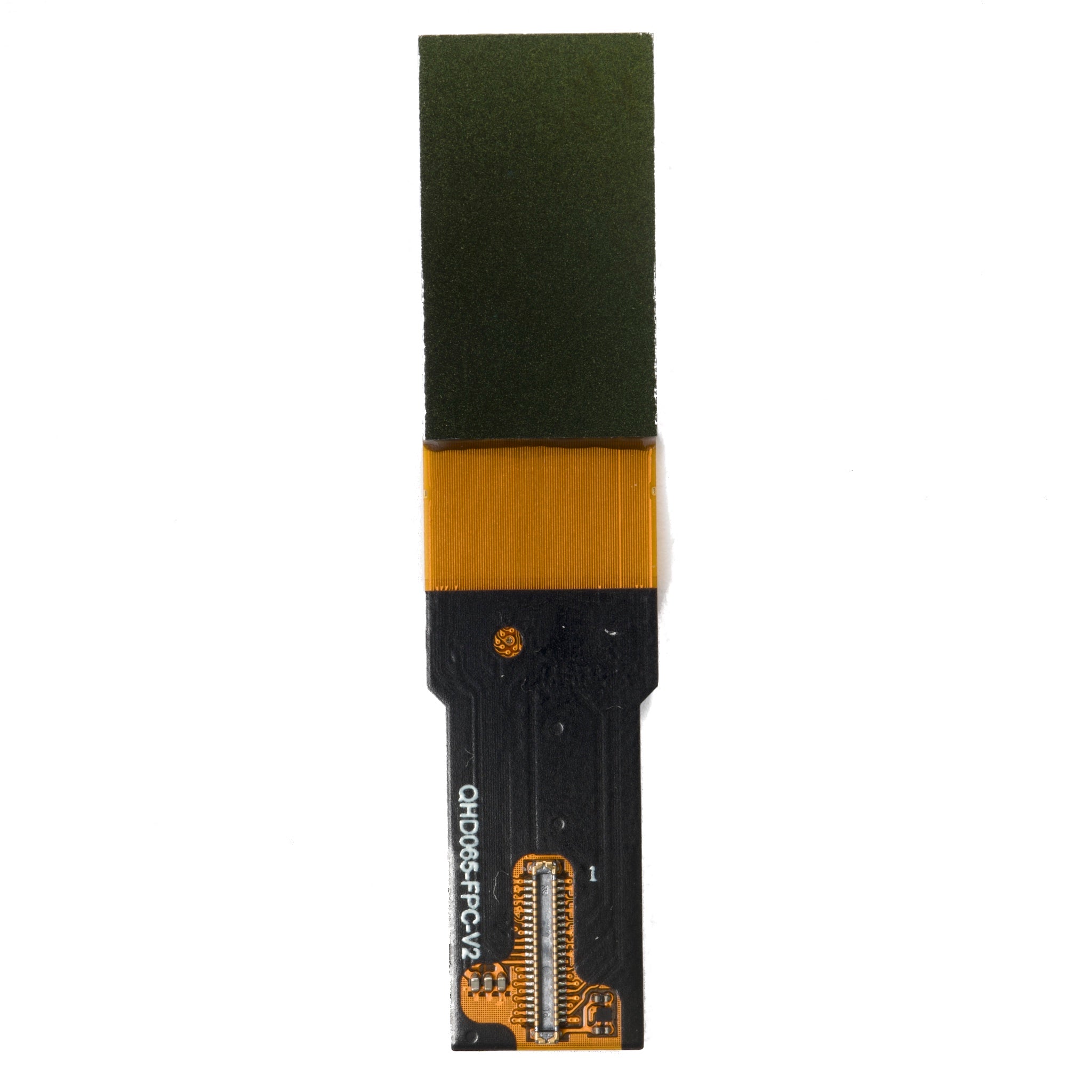
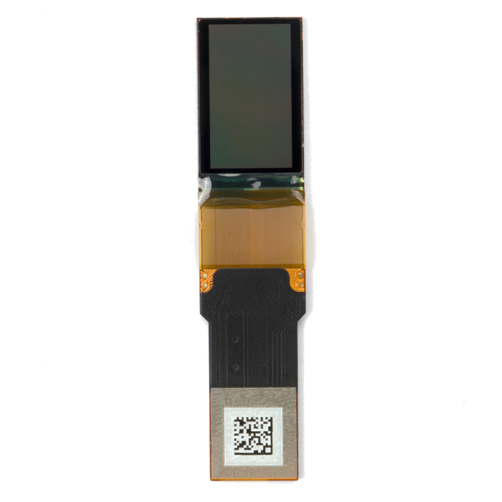
0.65” AMOLED Microdisplay 2560×1440 QHD – 1000-Nit MIPI Near-Eye Display for AR/VR & Optical Engines
- 💹 Enjoy a 20% discount for orders over 500
- 📉 A 15% discount is available for orders ranging from 200 to 499
- 🎁 A 10% discount is available for orders ranging from 50 to 199
- 🎁 A 5% discount is available when ordering 10-49
Interested in customizing this product? Get in touch with us.
Order samples, immediate delivery.
Factory bulk lead time: 3 weeks.
0.65” AMOLED Microdisplay 2560×1440 QHD – 1000-Nit MIPI Near-Eye Display for AR/VR & Optical Engines
0.65” AMOLED Microdisplay 2560×1440 QHD – 1000-Nit MIPI Near-Eye Display for AR/VR & Optical Engines
- 💹 Enjoy a 20% discount for orders over 500
- 📉 A 15% discount is available for orders ranging from 200 to 499
- 🎁 A 10% discount is available for orders ranging from 50 to 199
- 🎁 A 5% discount is available when ordering 10-49
Resources & Downloads
0.65" Silicon-Based OLED Microdisplay 2560 × 1440 with 4-Lane MIPI DSI
DMGGO0065QHNA is a 0.65-inch top-emitting, active-matrix-driven silicon-based OLED microdisplay with 2560 × 1440 resolution. It integrates signal enhancement circuits, row and column drive circuits, and logic control into a compact module designed for near-eye display systems requiring high resolution, high contrast, and wide operating temperature range.
The module uses a single MIPI DSI 4-lane input (D-PHY v1.1, 1.0 Gbps per lane) with DSC video compression support, an I2C control interface, an embedded temperature sensor, and PWM-mode brightness adjustment support within a 14.515 × 8.164 mm active area.
Technical Specifications
Sourced from official datasheet V1.0.0 (Nov 25, 2025) — for display selection, mechanical layout, and interface review.
| Parameter | Specification |
|---|---|
| Product Model | DMGGO0065QHNA |
| Display Technology | Top-emitting active-matrix-driven silicon-based OLED |
| Screen Size | 0.65 inch diagonal |
| Active Area | 14.515 mm × 8.164 mm |
| Resolution | 2560 × 1440 (2592 × 1472 reserved) |
| Pixel Arrangement | Hexagon |
| Pixel Dimension | 5.67 µm × 5.67 µm |
| Gray Level | 256 levels (8-bit) |
| Display Colors | Color; RGB 8:8:8 input mode supported |
| Video Interface | MIPI DSI 4-Lane, D-PHY v1.1 (1.0 Gbps per lane) |
| Video Compression | DSC supported |
| Control Interface | I2C (10 kHz to 400 kHz) |
| Typical Brightness | 1000 cd/m² |
| Recommended Brightness Range | 50 to 1000 cd/m² |
| Contrast Ratio | > 100000:1 |
| Luminance Uniformity | ≥ 90% @ 1000 cd/m² |
| Refresh Rate | 90 Hz |
| Supply Voltage | VDD 1.8V, VAN 5V, VEE -5V |
| Connector | HRS BM23PF0.8-40DP-0.35V (40-pin) |
| Operating Temperature | -20°C to +65°C |
| Storage Temperature | -55°C to +70°C |
Optical Characteristics
Brightness, contrast, uniformity, and pixel data for sample evaluation and display comparison.
1000 cd/m² Typ.
Typical brightness is 1000 cd/m² with a recommended brightness range of 50 to 1000 cd/m². The datasheet lists PWM-mode brightness adjustment and brightness adaptive adjustment support, while detailed brightness adjustment parameters are marked as TBD.
> 100000:1
The contrast ratio is specified as greater than 100000:1, enabled by the self-emissive silicon-based OLED technology with deep black levels.
≥ 90% @ 1000 cd/m²
Luminance uniformity is greater than or equal to 90% measured at 1000 cd/m², providing a reference for sample inspection and acceptance review.
90 Hz
The module operates at a 90 Hz refresh rate, supporting smooth motion display for near-eye viewing applications.
256 Levels (8-bit)
8-bit gray level with 256 steps supports color depth for near-eye image rendering. Image brightness and contrast digital adjustment are available via I2C registers.
5.67 µm Pixel Pitch
Hexagon pixel arrangement with 5.67 µm × 5.67 µm pixel dimension delivers high pixel density for fine near-eye detail rendering across the 14.515 × 8.164 mm active area.
Power Rails and Signal Details
DC characteristics, interface pins, and power-on sequence from the datasheet — for PCB design and processor-interface evaluation.
VDD 1.75 to 1.85 V
Typical value is 1.8 V with maximum current of 150 mA. Absolute maximum range is -0.3 V to 2.2 V. Check processor I/O compatibility before PCB layout.
VAN 4.9 to 5.3 V
Typical value is 5.0 V with maximum current of 100 mA. The datasheet lists VAN DC range as 4.9 to 5.3 V, while Absolute Maximum Ratings list VAN as -0.3 V to 5 V; confirm the allowable design margin with DisplayModule before final PCB design.
VEE -5.5 to -4.9 V
Typical value is -5.0 V with maximum current of 100 mA. The datasheet lists VEE DC range as -5.5 to -4.9 V, while Absolute Maximum Ratings list VEE as -5.0 V to 0.3 V; confirm the allowable negative-voltage design margin before final PCB design.
Functional Features
I2C-configurable modules integrated into the microdisplay for near-eye display applications.
Display Control & Enhancement
The microdisplay integrates signal enhancement circuits, logic control, and I2C-configurable functions for flexible integration into near-eye optical systems.
- Signal enhancement & logic control integrated on-chip
- I2C register-based brightness, contrast & mode control
- Inverse display & timed pixel shift for retention reduction
- Built-in temperature sensor with I2C readback
Video Signal Transfer Format
Supported MIPI DSI input formats and YCbCr-to-RGB conversion formulas — configured via register 0001H.
16-bit Mode
16-bit YCbCr 4:2:2 mode is supported. YCbCr to RGB conversion formula selectable: BT601 new, BT601 old, or BT709.
12-bit Mode
12-bit YCbCr 4:2:0 mode is supported. Suitable for compressed video input with reduced bandwidth requirements.
24-bit Mode
24-bit RGB 8:8:8 mode is supported for full-color direct input. Provides full color depth for near-eye display rendering.
Engineering Notes for Product Integration
Key considerations for hardware design, PCB layout, and optical system integration.
Power-On Sequence
Strictly follow the datasheet timing diagram for VDD, VAN, VEE, RESET, I2C initialization, and MIPI signal input. Incorrect sequencing may cause display abnormality or panel damage. Minimum timing values include t1 5 ms, t2 10 ms, t3 10 ms, t4 100 ms, and t7 5 ms.
MIPI Timing Configuration
Verify DSI clock, 4-lane configuration, and DSC compression settings against your host processor before PCB routing. The module uses D-PHY v1.1 with 1.0 Gbps per lane HS speed.
Connector Matching
Confirm the mating connector for the HRS BM23PF0.8-40DP-0.35V (40-pin) against the datasheet mechanical drawing before PCB layout. Verify FPC routing and pin assignment.
Optical System Integration
This is a microdisplay designed for near-eye display systems. An appropriate optical system is required to achieve the intended large-screen viewing effect. Confirm optical design requirements with your optics team.
Touch Configuration
Touch input is not specified in the datasheet. Do not assume touch support unless it is confirmed separately by DisplayModule.
Handling and Storage
Glass and silicon edges are easily damaged and must not be subject to physical stress. Short-term storage: -55°C to 70°C (≤ 100 hours). Long-term storage: 25°C ± 5°C in dry nitrogen or vacuum-sealed container. Avoid UV rays, ionizing radiation, bending, and heat sources.
Reliability Conditions for Project Evaluation
Temperature ranges and absolute maximum ratings — for environmental tolerance review before sample evaluation.
Helps customers review environmental tolerance for normal operation in near-eye display systems.
Short-term up to 100 hours. Long-term: 25°C ± 5°C in dry nitrogen or vacuum-sealed container.
VDD: -0.3V to 2.2V. VAN: -0.3V to 5V. VEE: -5.0V to 0.3V. Exceeding limits may affect product life and reliability.
Common Questions Before Sample Evaluation
What is the actual display size and pixel density?
0.65 inches diagonal with an active area of 14.515 mm × 8.164 mm and 5.67 µm pixel pitch in a hexagon arrangement.
What interfaces does the module support?
MIPI DSI (4-lane, D-PHY v1.1, 1.0 Gbps per lane) for video input and I2C (10 to 400 kHz) for control. DSC video compression is supported. See the Technical Specifications table for details.
What is the typical brightness and contrast?
Typical brightness is 1000 cd/m² with an adjustable range of 50 to 1000 cd/m². Contrast ratio is greater than 100000:1.
What is the operating temperature range?
Operating: -20°C to +65°C. Storage: -55°C to +70°C. See the Reliability section for absolute maximum ratings.
Does this module support touch input?
Touch input is not specified in the datasheet. Do not assume touch support unless it is confirmed separately by DisplayModule.
What video input formats are supported?
16-bit YCbCr 4:2:2, 12-bit YCbCr 4:2:0, and 24-bit RGB 8:8:8 modes. YCbCr-to-RGB conversion supports BT601 and BT709 formulas. See the Video Signal Transfer Format section.
What should be reviewed before PCB layout?
40-pin HRS connector match, MIPI lane mapping, power-on sequence, reset timing, power rails (VDD, VAN, VEE), and I2C slave address selection via SERADD pin.
Are there any TBD items in the datasheet?
Yes. Power consumption, temperature measurement details, and brightness adjustment specifics are marked as TBD in the current datasheet version (V1.0.0). Confirm with DisplayModule for the latest information.
Download the DMGGO0065QHNA Datasheet
Download the official datasheet for full electrical specifications, DC characteristics, DSI timing, power-on sequence, register map, video signal formats, and mechanical drawings to support your integration review.
Confirm dimensions, interface details, connector matching, and mechanical requirements before placing an order.