









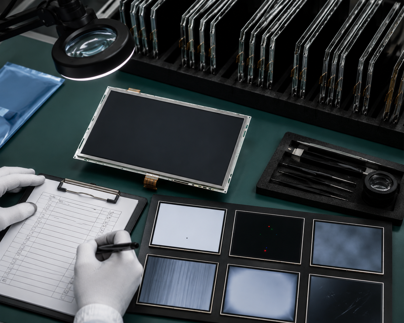
A display module should not be released to production just because it turns on. A screen can show an image and still have a bright pixel, a weak connector, low-gray mura, touch dead zones, a bent frame, or the wrong firmware.
Incoming inspection should answer three questions:
- Is the shipment the exact product and revision that were approved?
- Do the inspected units meet the agreed visual, electrical, and mechanical limits?
- Does any defect suggest that a larger part of the lot may be affected?
The checks below apply mainly to TFT LCD modules, LCD modules, OLED modules, AMOLED modules, and displays with integrated touch panels. Some checks apply only to one display type. For example, light leakage and backlight-film defects apply to LCDs, while low-gray banding and image retention need more attention on OLEDs.
IEC 61747-20-3:2016 gives visual-inspection rules and defect definitions for the active area of transmissive active-matrix color LCD modules. Its scope is useful, but it is not a universal acceptance specification for every display technology or finished product.[1]
Incoming inspection is not a replacement for product qualification, life testing, safety testing, or regulatory approval. Safety-related medical, automotive, aviation, and industrial products may need extra controls.
Set the Acceptance Rules
Do not begin inspection with vague requirements such as “good appearance,” “normal mura,” or “few bad pixels.” These phrases allow two inspectors to make different decisions on the same module.
The approved specification should define at least:
- Part number, revision, manufacturer, and approved production site
- Module outline, thickness, active area, viewing area, and connector position
- Interface, pin assignment, driver IC, touch controller, and firmware version
- Supply voltage, power sequence, signal timing, reset timing, and backlight current
- Inspection light, viewing distance, viewing angle, warm-up condition, and test brightness
- Test patterns and exact gray-code values
- Bright-pixel, dark-pixel, cluster, line-defect, mura, and light-leakage limits
- Cosmetic zones and limits for scratches, particles, stains, chips, cracks, and printing defects
- Critical, major, and minor defect definitions
- AQL, inspection level, sampling type, and lot-rejection rules
Before testing, compare the module with its current datasheet and drawing. The internal guide on reading a TFT LCD module datasheet explains where pinouts, timing, voltage limits, and initialization commands are normally found.
Document priority
The quality agreement should state which document wins when two requirements conflict. A common order is:
- Signed customer acceptance specification
- Approved customer drawing
- Approved quality agreement
- Approved limit samples
- Approved supplier specification
- Relevant industry standards
The exact order is a contract decision. An inspector should not choose the easier requirement after finding a defect.
Golden and limit samples
A golden sample shows a normal acceptable product. A limit sample shows the boundary between pass and fail. They are not the same.
Each limit sample should have an ID, defect description, approval date, approved viewing condition, photographs or measurement data, storage method, and review date. Display samples can become scratched, dirty, yellowed, or dimmer over time, so they need regular review.
If a new defect is not covered by the specification, place the affected material on hold. Quality, engineering, purchasing, and the product owner should make a written temporary decision. Add the agreed rule to the next revision of the inspection specification.
Define the Inspection Lot
A sampling result is meaningful only when the lot is reasonably consistent. One lot should normally contain modules with the same:
- Manufacturer and production site
- Part number and revision
- Panel source and driver IC
- Touch-controller and firmware version
- Backlight, FPC, adhesive, and cover-lens design
- Production process and defined date-code range
- Packaging method
Do not combine unrelated batches because they arrived on the same truck. If one date code used a different polarizer, adhesive, driver IC, or lamination setting, inspect it as a separate lot.
Record the purchase order, supplier lot, date code, serial range, revision, quantity, carton count, pallet count, and inspection date. Missing traceability is itself a risk because the affected production period cannot be isolated later.
Keep reworked, previously rejected, supplier-sorted, engineering, replacement, and unapproved-change material separate from normal production stock. For custom projects, define traceability before mass production; the internal article on custom LCD development explains where FPC, backlight, touch, adhesive, and cover-lens changes enter the process.
Use AQL Correctly
AQL means acceptance quality limit. It is an index used in an approved sampling plan. It does not mean that the supplier is allowed to ship exactly that percentage of defective modules.
ISO 2859-1:2026 defines AQL-based, lot-by-lot attribute sampling and includes single, double, and multiple sampling schemes.[2] ISO 2859-2:2020 is intended for isolated or short series of lots where the switching rules used for continuing lots do not apply.[3] ANSI/ASQ Z1.4-2003 (R2018) is another attributes-sampling system for continuing lots and includes normal, tightened, and reduced inspection.[4]
Use the standard and edition named in the supplier agreement. Do not use an old table copied from a blog, spreadsheet, or another product.
Single sampling
For a single-sampling plan:
- Confirm the lot size and inspection level.
- Use the approved table to find the sample-size code and sample quantity.
- Find the acceptance number (Ac) and rejection number (Re) for each defect class.
- Select the sample randomly.
- Inspect all selected units.
- Compare each defect count with its own Ac and Re.
Ac is the highest count that still allows acceptance. Re is the lowest count that causes rejection. Major and minor defects are normally judged separately.
Double and multiple sampling
In double sampling, the first sample may lead to acceptance, rejection, or a required second sample. If the second sample is required, use the cumulative result and the approved second-stage limits.
Do not take an extra sample after a final rejection just to obtain a passing result. A later sample is valid only when it is part of the approved sampling plan or a separately approved investigation that does not erase the original decision.
Defective units and defect counts
The plan must say whether it counts defective units or individual nonconformities.
- Defective-unit method: one module with a bright pixel, a scratch, and a label error normally counts as one defective module, classified by its most serious problem.
- Nonconformity method: the same module may count as three separate defects.
Do not switch counting methods during an inspection. Also, do not add major and minor defects together unless the approved plan says to do so.
Example decision
The following numbers are fictional and only show the decision logic. They must not be used for a real shipment.
Assume a single-sampling plan requires 125 units:
- Critical: reject if one is found
- Major: Ac 3, Re 4
- Minor: Ac 7, Re 8
- Two major and five minor defects: pass under this fictional example.
- Four major defects: reject.
- One critical defect: reject.
- Three major and eight minor defects: reject because the minor count reached Re.
Zero acceptance in the sample does not prove that the entire lot contains zero critical defects. Safety-critical features may need 100% automated checks, error-proofing, process controls, and full traceability.
Random selection
Take samples from different pallets, cartons, tray levels, serial ranges, and date codes that belong to the same defined lot. Do not inspect only the nearest cartons or supplier-prepared “inspection samples.”
A practical method is to divide the required quantity across all pallets, randomly choose cartons, and then take units from different positions inside each carton. Record where each inspected unit came from.
If several nearby units have the same defect, continue the original sampling decision but also investigate the local pattern. The defect may be limited to one tray, carton, serial range, shift, or date code.

Set Up the Inspection Station
Visual results change with light, distance, angle, panel temperature, brightness, test pattern, warm-up time, and pressure from the fixture. ISO 9241-307:2008 recognizes that display testing depends on the display technology, task, and use environment.[5]
Use customer-approved conditions first. If none exist, create an internal method and verify it with known good, borderline, and rejected samples.
Example starting conditions
| Check | Example starting condition |
|---|---|
| Surface inspection | Diffuse white light, about 600–1,000 lux |
| Normal powered inspection | About 100–300 lux |
| Bright-pixel check | Dark area, normally below 5 lux |
| LCD light-leakage check | Dark area, normally below 5 lux |
| Viewing distance | About 30–50 cm |
| Viewing direction | Near perpendicular unless the product specifies another angle |
| Warm-up | Often 15–30 minutes, followed by a stability check |
| Brightness | One fixed approved setting |
These are reasonable factory starting points, not universal acceptance limits. ISO 9241-305:2008 covers optical laboratory methods, while ISO 9241-306:2018 covers field assessment in different use conditions.[6][7]
Gray patterns
“5% gray” is not precise enough by itself. It may refer to a digital code level or to measured light output after gamma correction. Record the bit depth, signal range, RGB code, gamma setting, and pattern-file version.
For example, RGB 13/13/13 is close to 5% of the code range in an 8-bit full-range signal, but it does not mean the screen emits 5% of its maximum luminance.
Warm-up and stability
Do not rely only on a timer. Confirm that luminance, current, and panel temperature have stopped changing quickly. A practical internal rule can require two readings taken a few minutes apart to stay within an agreed difference.
Tools and repeatability
A basic station may use an ESD-safe bench, regulated supply, approved interface board, correct cable, pattern generator, current meter, caliper, magnifier, illuminance meter, approved cleaning material, and camera. More demanding checks may need a luminance meter, colorimeter, imaging photometer, microscope, touch-test software, temperature chamber, or final-assembly fixture.
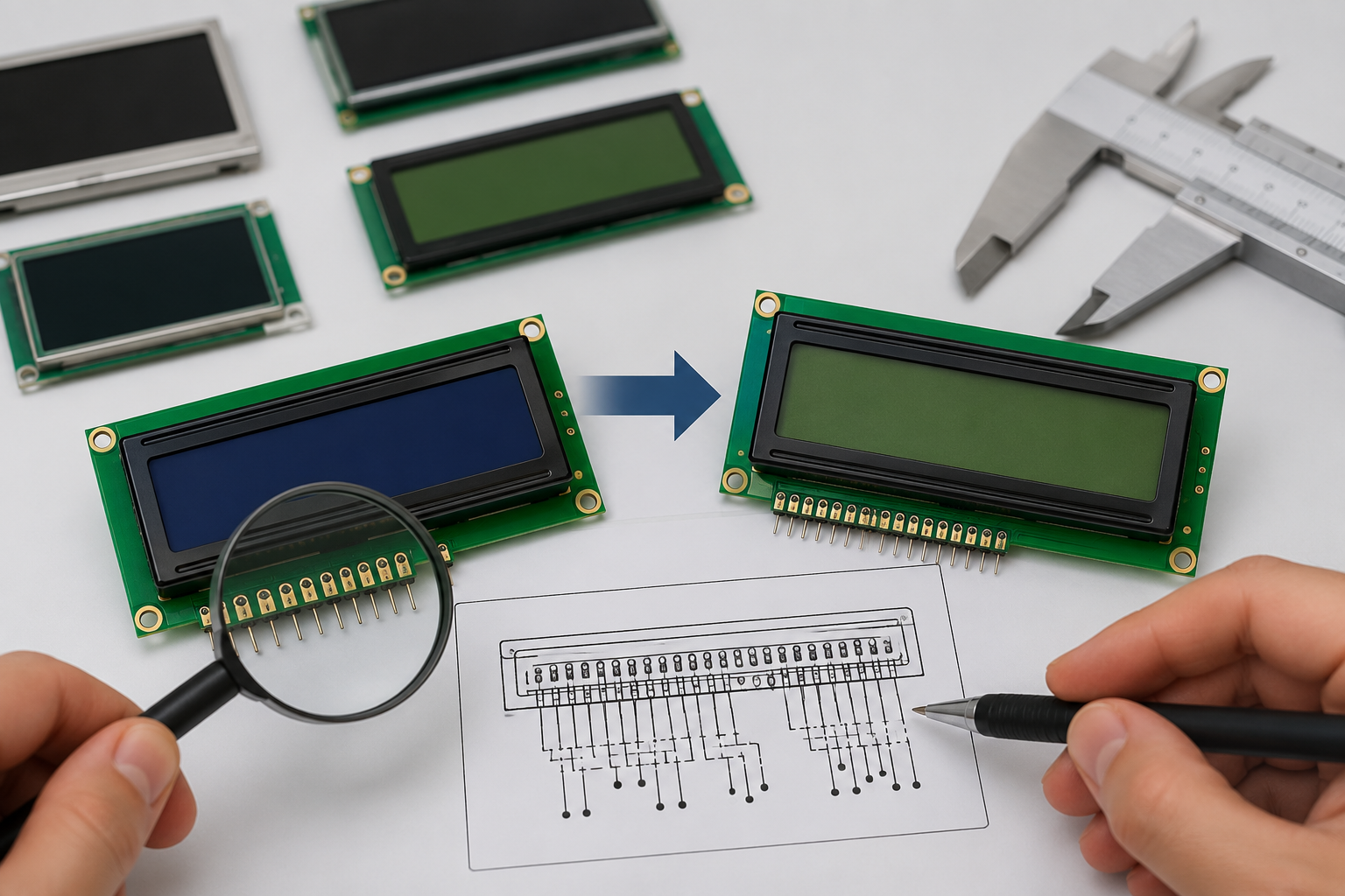
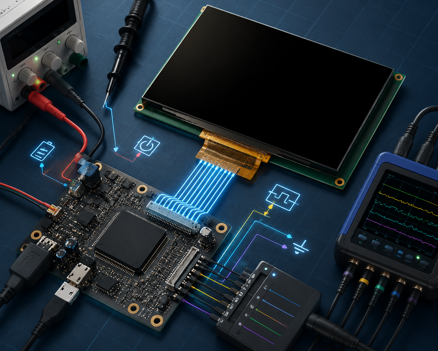
The test board must match the interface, pinout, voltage, lane count, timing, and initialization of the module. The internal guide to display interfaces can help separate interface problems from panel defects. A board from the display adapter collection may simplify testing, but compatibility still has to be confirmed for the exact module.
Instrument resolution is not enough. Accuracy, repeatability, calibration, fixture method, and measurement uncertainty also matter. NIST explains measurement uncertainty as the spread of values that could reasonably be linked to the measured quantity.[8]
Check inspector agreement by asking several trained inspectors to judge the same limit samples. If their decisions often differ, improve the lighting, defect wording, photographs, samples, or training.
Verify Identity and Packaging
Identity
Before applying power, check the supplier and buyer part numbers, revision, date code, lot code, FPC marking, connector, driver-board marking, touch-controller version, and firmware ID where it can be read.
Two modules can have the same size and connector but different pin assignments, interface voltage, color order, reset timing, initialization commands, backlight current, or touch firmware. Stop before power-on if a difference is not explained by approved documents.
Packaging
Check for crushed or wet cartons, broken seals, bent trays, loose modules, missing separators, trapped FPCs, sharp tray edges, broken glass, dust inside sealed packaging, and pressure marks on the screen.
If the module is identified as ESD-sensitive, its packaging and handling should follow the approved ESD-control plan. ANSI/ESD S541-2026 is the current ESD Association packaging-material standard for ESD-susceptible items.[9]
Record packaging and product defects separately:
- Crushed carton, modules undamaged: packaging defect.
- Crushed carton, modules cracked: packaging and product defects.
- Carton intact, modules scratched: likely manufacturing or internal packing issue.
If one carton is damaged, inspect nearby units to find the affected scope, but keep that investigation separate from the original statistical result.
Check Mechanical and Cosmetic Quality
Dimensions and fit
Measure overall length, width, thickness, active-area position, viewing-area position, mounting points, connector position, FPC length, bracket position, gasket thickness, and adhesive position where they affect assembly.
Judge both the upper and lower drawing limits, not only the nominal value. State whether film, foam, adhesive liners, and gaskets are included in the measurement. Do not stretch an FPC to make its length pass.
A simple assembly fixture often finds problems that separate measurements miss, such as connector interference, excessive thickness, FPC routing problems, or frame pressure. IEC 61747-10-1:2013 lists mechanical test methods for LCD devices, but incoming fit checks should still follow the exact product drawing and assembly design.[10]
Scratches and particles
First inspect with the protective film installed. Remove the film only from designated samples when a suspected defect must be confirmed.
For a scratch, record its location, length, width, material layer, and whether it is visible with the display on and off. Identify whether it is on the removable film, cover glass, anti-glare coating, polarizer, touch layer, printed border, or an internal layer.
Do not drag a fingernail over an optical surface. It can add contamination or damage a coating. Use approved cleaning, magnification, or a non-destructive measurement method.
For a particle:
- If it moves or disappears after cleaning, it is probably on the surface.
- If it shifts relative to the pixels when the viewing angle changes, it may be between bonded layers.
- If it stays fixed at the pixel plane, it may be internal contamination or a pixel defect.
- If it appears only when an LCD backlight is on, it may be inside the backlight stack.
These observations help with screening but do not prove the root cause. Final confirmation may require microscopy or supplier analysis.
Glass edges
Separate a small rounded chip from a crack, shell fracture, corner break, or sharp edge. Record length, width, depth, direction, and distance from the seal, active area, and mounting pressure.
Reject cracks unless an approved specification defines a safe limit supported by engineering evidence. A crack can grow during assembly, vibration, temperature change, or impact. Long environmental or endurance checks belong to product validation rather than ordinary receiving inspection; IEC 61747-10-2:2014 lists environmental and endurance methods for LCD devices.[11]
FPC and connector
Check for cuts, creases, punctures, exposed copper, delamination, damaged stiffeners, dirty or oxidized contacts, bent fingers, wrong fold lines, lifted reinforcement, and components that touch the housing.
Confirm that the connector lock closes, the stiffener matches the connector, and the bend does not cross a sensitive solder joint or sharp copper-trace corner. Move the FPC only within its normal working range. Repeated insertion or sharp bending can create a new defect.
For COG products, inspect the glass edge, bonded driver area, FPC alignment, and handling protection carefully. The internal COG LCD module guide explains the basic structure and common integration points.
Power and Functional Checks
Safe startup
- Confirm the part number and pin assignment.
- Inspect the connector and exposed circuits for damage or debris.
- Set the correct voltage and a safe current limit.
- Connect the approved power and signal cables.
- Apply the required power and reset sequence.
- Load the correct initialization commands.
- Watch startup current and image behavior.
Check startup time, image stability, resolution, orientation, RGB/BGR order, refresh behavior, current, LCD backlight, dimming, sleep, wake, and reset.
Watch for flicker, flashing, random lines, missing rows or columns, image tearing, rolling, delayed startup, abnormal heat, noise, odor, and failures that appear after warm-up.
Black-screen checks
A black screen does not immediately prove that the module is defective. Check the supply voltage, current, reset, interface cable, timing, initialization commands, image-data output, and LCD backlight. Then compare the suspected module on a known-good fixture and a known-good module on the same fixture.
AMOLED modules can remain black when power rails, reset, initialization, or emission control are in the wrong order. The internal article on AMOLED power sequence explains this fault in more detail.
Avoid hot plugging unless both the module and fixture are designed for it.
Check Pixel Defects
A color pixel normally contains red, green, and blue subpixels. The specification must say whether it counts subpixels, complete pixels, clusters, or line defects. ISO/TR 9241-310:2010 gives guidance on the visibility and specification of pixel defects, but it does not set one universal pass/fail limit for every display.[12]
Confirm the defect
- Clean the approved outer surface.
- Check whether the mark is on the protective film.
- Show black, white, red, green, and blue patterns.
- Move or replace the pattern to rule out an image-file problem.
- Restart the module and reconnect the cable.
- Confirm that the mark stays at the same physical position.
Bright pixels
Use a black pattern. A red, green, blue, or white dot that remains lit is a bright defect. A white dot may involve all three subpixels. The specification must say whether to count it as one full pixel or three subpixels.
Dark pixels
Use white, red, green, and blue patterns. A point that is dark only on the red pattern usually indicates one dark red subpixel. A point that is dark on all primary-color patterns may be a complete dark pixel.
Unstable pixels and lines
Some pixels flicker, respond slowly, change with temperature, or fail only at low gray levels or one refresh rate. Record the gray code, brightness, refresh rate, temperature, and time after startup.
A full horizontal or vertical line should not be counted as hundreds of bad pixels. Treat it as a line or drive defect, normally at a major level.
Clusters and zones
Define a cluster by pixel distance or physical distance. Two nearby defects are usually more noticeable than two defects far apart.
Zones should follow the real user interface:
- Zone A: important values, warning icons, payment amounts, crosshairs, or frequently used controls.
- Zone B: the rest of the visible active area.
- Zone C: the hidden border or non-viewing area.
A hidden crack or conductive particle does not become acceptable simply because it is in Zone C. If a defect crosses two zones, apply the stricter rule unless the specification says otherwise.
Check Mura and Uniformity
Mura means a visible patch, cloud, band, spot, gradient, tint, dark corner, bright edge, or pressure mark. It may be invisible on white and clear at low or medium gray.
The SID International Committee for Display Metrology maintains the Information Display Measurements Standard, which contains standardized display-measurement methods, including spatial measurements used for uniformity and mura work.[13]
LCD and OLED differences
For LCD, check pressure mura, backlight hotspots, optical-film wrinkles, light-guide variation, edge brightness, and broad cell non-uniformity.
For OLED and AMOLED modules, check low-gray vertical bands, dark patches, color tint, uneven compensation, and persistent image retention. The internal OLED versus LCD guide explains why the two technologies show different defects.
IEC 62341-6-1:2025 sets measurement conditions and methods for OLED optical and electro-optical parameters.[14] Image sticking and OLED lifetime need separate controlled methods; IEC 62341-5-3:2019 covers those measurements for OLED panels and modules.[15] A short incoming check cannot prove long-term OLED life.
Test method
Use black, low-gray, medium-low-gray, medium-gray, high-gray, and white patterns with exact RGB codes. Fix the brightness, ambient light, viewing distance, direction, warm-up, module temperature, and refresh rate.
For each visible area, record:
- Pattern and RGB code
- Location and size
- Whether it is visible from the approved direction
- Whether it is visible in the normal user interface
- Whether it changes after assembly
Global and local defects
Global uniformity describes a broad brightness difference across the screen. Local mura is a smaller defect that differs from nearby pixels. A display can pass a five-point or nine-point uniformity check and still have a local patch between the measured points.
One simple global calculation is:
Global uniformity (%) = Lmin ÷ Lmax × 100
The contract must define the formula, pattern, measurement points, spot size, instrument geometry, brightness, warm-up, and pass limit. Other formulas are also used, so results from different formulas should not be compared directly.
IEC 61747-30-1:2012 covers measurements for transmissive LCD modules and notes that a combined touch panel can affect accuracy; this is one reason the exact measurement stack must be stated.[16]
Assembly stress
First test the bare module in a stress-free holder. Then install it in a representative housing with the approved foam, clips, adhesive, connector routing, and screw torque. Repeat the gray patterns.
If mura becomes worse after assembly, check screw torque, frame flatness, foam thickness, bezel pressure, adhesive position, and connector interference. Do not press the panel with a finger to “test” the mura.
Check LCD Light Leakage
This check applies to LCD modules, not to self-emissive OLED modules.
Use a black pattern in a controlled dark area. Fix the backlight level, viewing direction, distance, warm-up, and camera exposure. Look for bright corners, edge leakage, local spots, pressure marks, and misplaced backlight films.
Separate front-view leakage from glow that appears only at an off-axis viewing angle. Do not reject a module only from an automatically exposed phone photo; night mode and long exposure can make a small difference look severe.
IEC 62595-2-1:2016 gives measurement conditions and methods for the electrical and optical properties of LED backlight units used with LCDs.[17]
Check Touch Operation
Use software that shows the touch point and records a continuous path. Test the corners, edges, center, slow drag, fast drag, horizontal and vertical lines, multi-touch, sleep, and wake.
Look for broken paths, jumps, wavy tracks, missing edge areas, swapped finger IDs, false touches, and touch points that appear without contact.
Check that the touch point matches the displayed location and that screen rotation does not create a coordinate error.
Touch behavior can change with cover-glass thickness, optical adhesive, grounding, metal housing, charger noise, display switching, PWM dimming, gloves, water, and temperature. Routine receiving inspection may use the approved module fixture, but first articles and engineering-change lots should also be checked in a representative final assembly.
For industrial products, the internal guide to TFT LCDs for industrial HMI gives more detail on touch options and system integration.
Classify and Record Defects
Defect levels
Critical defects create a safety, legal, or severe product risk. Examples include smoke, short circuit, dangerous sharp glass, unauthorized material, or failure of a safety warning.
Major defects affect function, assembly, reliability, normal use, or customer acceptance. Examples include no image, intermittent display, severe flicker, missing lines, wrong interface, excess bad pixels, severe mura, touch dead zones, wrong dimensions, or a damaged FPC.
Minor defects reduce appearance or workmanship without stopping normal use. Examples include a small hidden mark, slight label shift, or minor printing defect.
Do not classify only by size. A small bright pixel in a warning area can matter more than a larger mark hidden under the housing.
Defect catalog
Each catalog entry should show the defect name, correct test pattern, common false causes, measurement method, zone rule, defect level, pass limit, fail example, and required action.
Use clear descriptions such as:
Green bright subpixel visible on full black, 16 mm left of screen center, Zone A.
Dark cloud-shaped mura, about 20 mm × 12 mm, visible at RGB 26/26/26 and 64/64/64.
Evidence
Record the serial number, lot, date code, carton, defect type, class, location, dimensions, pattern, RGB code, brightness, light level, distance, direction, temperature, voltage, current, refresh rate, fixture, cable, software version, film status, assembly state, and time needed for the defect to appear.
Take one full-screen photograph to show location and one close-up to show the defect. Keep the original image. If contrast is changed for analysis, save the edited copy separately and state what was changed.
Decide and Control the Lot
Compare each defect class with the approved sampling limits. Possible decisions include accept, reject, quarantine, technical investigation, 100% sorting, supplier return, or an approved one-time deviation.
Do not release a rejected lot because production is waiting. A deviation should state the exact lot and quantity, known defect, affected product, risk, extra controls, approver, and expiration.
Typical responsibilities are:
- IQC inspects and isolates material.
- Engineering confirms the technical finding.
- Quality owns the risk and lot decision.
- Purchasing coordinates supplier action.
- The product or customer authority approves any deviation when required.
Sorting and rework
A 100% sorting instruction should define the defect, pattern, light, distance, limit sample, inspector training, traceability, separation method, and audit plan.
The supplier should report the quantity sorted, quantity rejected, defect breakdown, date, inspectors, test conditions, new lot ID, and rejected-unit disposition. Audit the sorted material before release.
Visual fatigue can reduce pixel and low-gray mura detection. Use rest periods, limit-sample checks, supervisor audits, and random reinspection.
Root cause
A symptom is not a root cause. A missing line may come from the cable, test board, connector, FPC, driver bond, or glass trace. First replace the cable, use a known-good fixture, restart the module, and confirm that the line stays at the same location.
A corrective-action report should state the affected scope, containment, verified cause, corrective action, prevention, verification data, owner, and completion date. “Operator error” is incomplete unless the supplier explains why the process allowed the error and why inspection did not catch it.
Track Supplier Quality
A lot can pass AQL while the process is slowly getting worse. Track clearly defined measures:
Lot rejection rate (%) = rejected lots ÷ inspected lots × 100
Unit defective rate (%) = defective modules ÷ inspected modules × 100
Defects per unit = total nonconformities ÷ inspected modules
Escaped unit rate (%) = defective modules found after release ÷ released modules × 100
If you count escaped defects rather than defective modules, use a separate measure such as defects per million released modules. Do not mix defect counts with unit counts in one formula.
Break the data down by supplier, factory, line, date code, revision, panel source, backlight source, touch-controller version, and engineering-change status. Use a Pareto chart to find the largest loss categories and a trend chart to see gradual change.
Do not compare displays with different resolutions only by the number of bad subpixels. Also track the percentage of modules with pixel defects and, where useful, defects per million subpixels.
Release Checklist
- The part number, revision, firmware, lot, and traceability are confirmed.
- The sample was selected using the approved plan.
- The test fixture, patterns, light, brightness, distance, angle, and warm-up were controlled.
- Suspected pixel, mura, particle, scratch, and electrical defects were confirmed before counting.
- Defects were classified, zoned, measured, and counted using one consistent method.
- No critical defect, unexplained intermittent failure, mixed revision, unknown change, or unstable fixture issue remains.
- The lot decision was approved by an authorized person.
Stop release when product identity is uncertain, revisions are mixed without control, limits are missing, a critical defect is found, the fixture is unstable, an engineering change is unapproved, or traceability is missing.
Conclusion
A reliable incoming inspection uses the correct product documents, a clear lot definition, an approved sampling plan, controlled viewing conditions, and consistent defect counting. AQL supports a lot decision, but it does not prove that every unit is perfect. Repeated sorting may contain one shipment; only a verified process correction prevents the defect from returning.
Leave a comment
This site is protected by hCaptcha and the hCaptcha Privacy Policy and Terms of Service apply.