

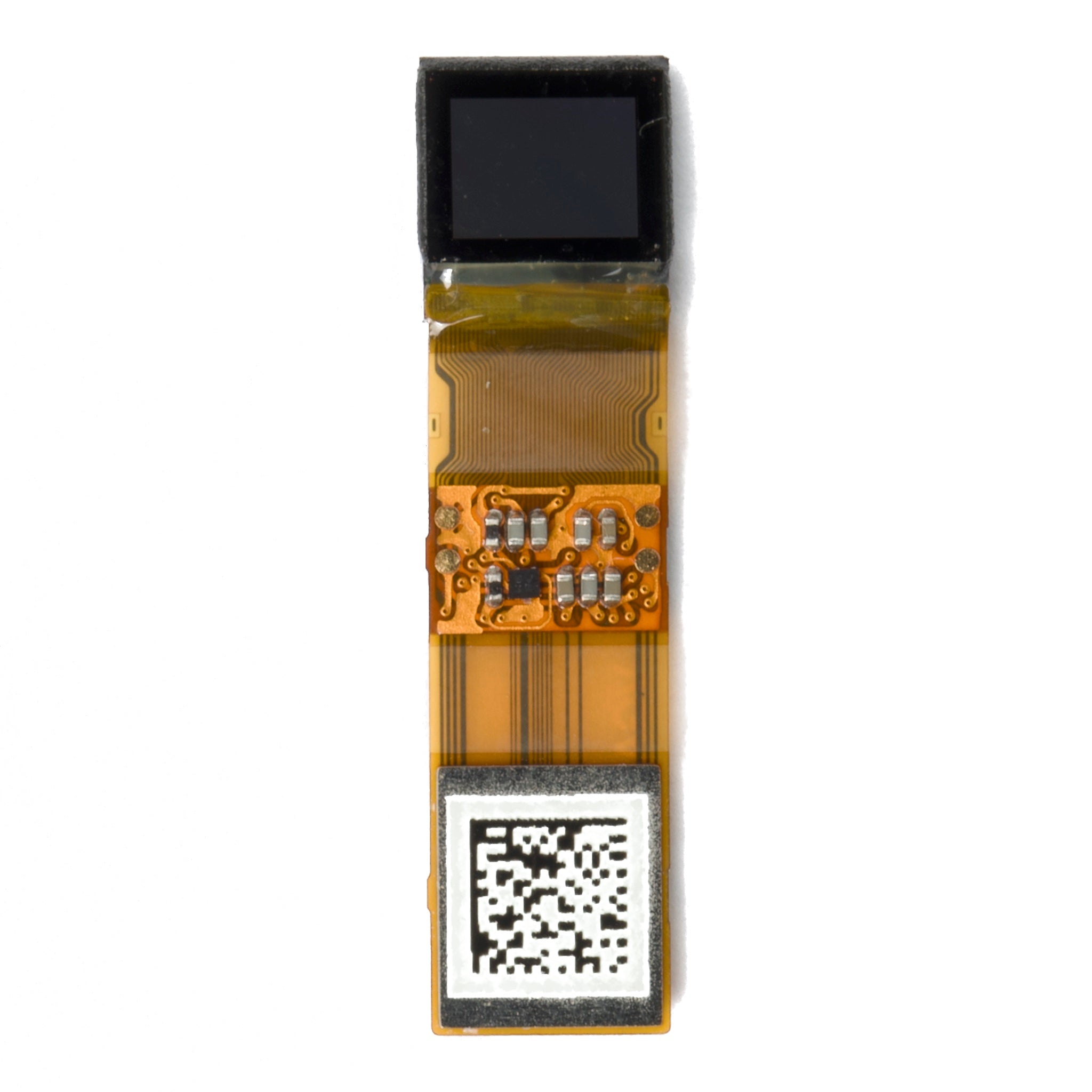
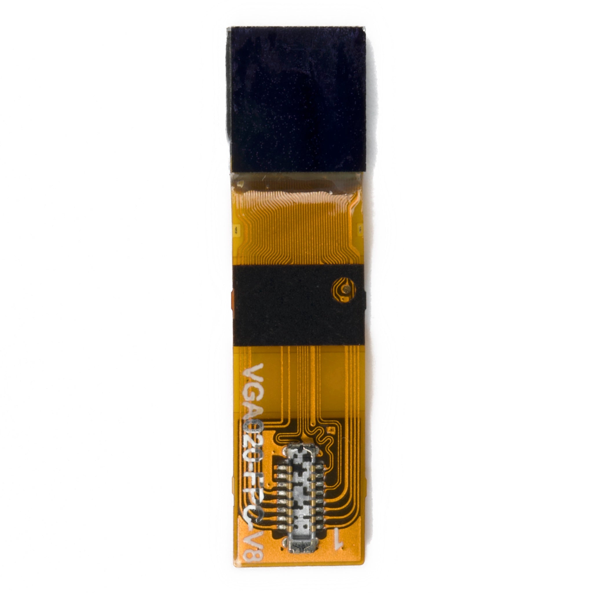
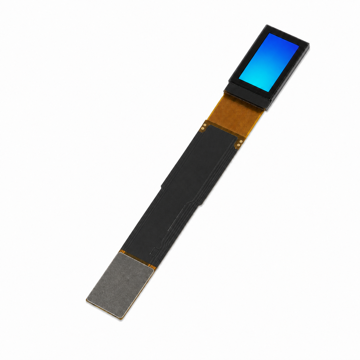
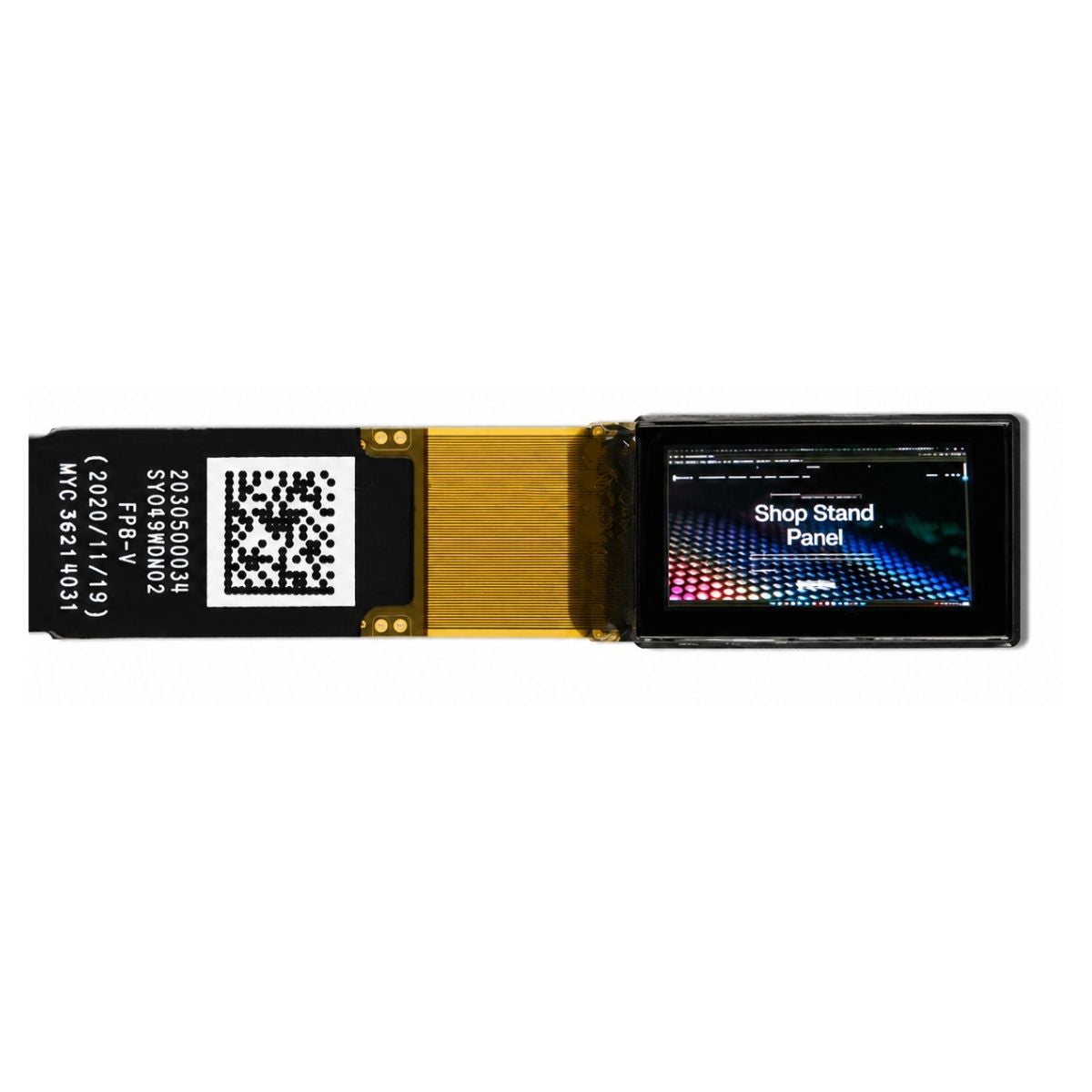


Micro OLED or Micro LED for Near-Eye?
For a full-color EVF or AR prototype, start by evaluating Micro OLED with a matched driver board. For a compact, very bright monochrome AR overlay, evaluate Micro LED. Neither technology wins every near-eye design: the choice depends on color, brightness through the optics, resolution, power, and host compatibility. Micro OLED already has manufacturer-listed RGB panels for viewfinders and AR headsets [1]. Micro LED offers substantial brightness potential, but that does not establish a full-color system advantage over OLED [2]. The Micro LED example examined here is a monochrome JBD panel, not a full-color alternative [3].
This micro OLED vs micro LED comparison is a specification-based selection guide, not a hands-on performance test. Manufacturer examples establish what particular parts list; they do not establish identical test conditions, current distributor stock, or a guaranteed delivery schedule.
Micro OLED vs Micro LED at a Glance
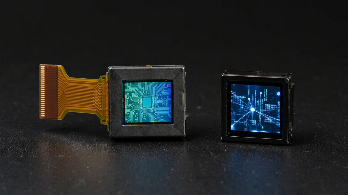
Micro OLED uses organic emitters on a silicon backplane. Micro LED uses inorganic LED emitters; near-eye implementations combine these with drive electronics. Both are self-emissive technologies, but emitter material alone does not determine the finished module's brightness or energy use [1][2].
| Selection question | Micro OLED | Micro LED |
|---|---|---|
| Does the content require full color? | Sony lists RGB OLED microdisplays for EVFs and AR headsets [1]. | The JBD example here is monochrome. A full-color candidate needs a separate specification [3]. |
| How much panel brightness is available? | Sony ECX350F lists 10,000 cd/m² maximum luminance at a stated 100% duty ratio [1]. | JBD lists up to 10 million nits for green on its 0.13-inch monochrome display [3]. These are not matched-condition measurements. |
| What resolution and refresh are supported? | ECX350F lists 1920 × RGB × 1080. Obtain refresh and timing requirements for the exact revision [1]. | The cited JBD display lists 640 × 480 and 60/75 Hz [3]. |
| Will the host and driver board work? | Sony lists MIPI D-PHY plus DSC for ECX350F, but LVDS for several other OLED parts [1]. | The cited JBD display lists MIPI/QSPI [3]. Confirm the detailed protocol and timing. |
| Which uses less power? | Request panel and board power at the required content, brightness, and refresh. | JBD lists 60 mW typical [3]. It does not establish the power needed at maximum green brightness or the power of a full-color optical engine. |
| Which lasts longer? | Compare lifetime and image-retention limits under the intended operating conditions. | Inorganic emitters offer durability potential [2]; obtain a part-specific lifetime specification rather than assuming a guaranteed service life. |
| What is the procurement risk? | Confirm panel revision, supported board, sample availability, and lead time together. | Confirm the same items, especially color configuration. Manufacturing challenges discussed in research do not establish a supplier's current price or lead time [2]. |
Which Is Better for an EVF or Full-Color AR?
Micro OLED is a practical starting point when the image must contain color video, camera menus, or detailed graphics and a compatible panel-and-board combination can be sourced. Sony's product table lists RGB resolutions and EVF applications, as well as the ECX350F AR-headset example [1]. That supports evaluating the category; it does not prove that any panel in the category will fit your optical or electrical design.
For an enclosed EVF, evaluate the image through the intended eyepiece rather than selecting the brightest bare panel. For see-through AR, establish the required visibility against ambient light and the optical engine's luminance transfer before choosing a panel. The AR panel requirements guide groups the resolution, field-of-view, refresh, and brightness decisions that belong in the same specification.
Use the Micro OLED collection to identify candidates, then request the exact panel datasheet and a confirmed driver-board pairing. A bare panel is not a finished viewing system: the distinction between a panel and a Micro OLED monitor matters when comparing quoted hardware.
When Does Micro LED Make More Sense?
A monochrome Micro LED candidate is worth evaluating when the content is navigation arrows, instrument symbols, or a single-color overlay and high source luminance is a central requirement. JBD's official example lists a 0.13-inch display, 4-micrometer pixel pitch, approximately 6,350 PPI, and monochrome red, green, or blue configurations; its 10-million-nit brightness listing is specifically green [3]. Those figures describe the product family and color configuration, not an RGB display.
Full-color Micro LED should not be ruled out simply because this comparison uses a monochrome example. Research discusses RGB integration and color-conversion approaches, along with efficiency and manufacturing challenges [2]. Before choosing a full-color candidate, obtain its resolution, brightness at a defined white point and average picture level, uniformity limits, supported interface, sample status, and production plan.
The Micro LED technology overview provides background terminology. Use the manufacturer's exact part specification, rather than a technology overview, for the final comparison.
Compare Brightness at the Eye, Not Just Panel Nits
A nit is a candela per square meter. The Sony and JBD examples demonstrate why brightness must be compared by part and color: the former lists an RGB OLED panel, while the latter's highest listed value applies to green monochrome [1][3]. Their advertised values do not constitute an equal-content, equal-power comparison.
Do not treat 4,000 nits as a ceiling for Micro OLED. Sony's current product table includes ECX350F at 10,000 cd/m² maximum luminance with a 100% duty ratio [1]. Duty ratio is not the same thing as average picture level, and that listing alone does not establish sustained full-white brightness at every temperature. Request measurement conditions and brightness derating for the exact part.
An illustrative luminance budget
For a preliminary budget, define an effective luminance-transfer factor for the specified panel, optical engine, pupil position, field angle, and measurement geometry. If that factor is assumed to be 0.05 or 0.10, multiply panel luminance by it to obtain the estimates below. These are chosen arithmetic assumptions, not measured waveguide efficiencies; a total optical-power efficiency cannot automatically be substituted for a luminance-transfer factor.
| Assumed panel luminance | Estimated eye-side luminance at factor 0.05 | Estimated eye-side luminance at factor 0.10 |
|---|---|---|
| 1,000 nits | 50 nits | 100 nits |
| 3,000 nits | 150 nits | 300 nits |
| 5,000 nits | 250 nits | 500 nits |
Replace the assumed factor with supplier optical data and validate the result through the assembled engine. Do not assume the two display technologies have identical optical losses: spectrum, panel geometry, coupling, and the selected optic can change the result. The waveguide fabrication discussion explains why the optic itself is a separate part of module evaluation.
Request small-window, full-white, and representative-content luminance with average picture level, temperature, and drive settings recorded. Text cards and video should be evaluated separately if they impose different content loads. High panel luminance alone proves neither outdoor readability nor eye safety.
Resolution and Driver-Board Matching Can Decide the Choice
Compare angular detail, not PPI alone
For a first-order estimate, horizontal pixels per degree equals horizontal pixel count divided by horizontal field of view in degrees. At the same field of view, panel pixel count determines this average; making the panel physically smaller raises PPI but does not by itself increase angular detail. Optical distortion and image quality still need evaluation through the actual eyepiece.
Calculate the video payload
For an illustrative uncompressed 1920 × 1080 stream at 24 bits per pixel and 90 Hz, active-image data is 1920 × 1080 × 24 × 90 = 4.478976 Gbit/s, or about 4.48 Gbit/s. Adding an assumed 20% planning allowance gives about 5.37 Gbit/s. That allowance is not a MIPI requirement: actual link demand depends on timing, packetization, operating mode, compression, and implementation.
MIPI Alliance defines DSI-2 as a processor-to-display interface specification [4]. Do not infer panel compatibility from that family name. Confirm the supported protocol, lane count, lane rate, command set, initialization, and compression behavior on both sides. The Micro OLED MIPI and host-bandwidth guide puts those checks alongside host selection.
Match the physical interface and power sequence
MIPI D-PHY is a physical-layer specification [5], not proof that two panels accept the same video stream. Sony's OLED lineup itself includes both LVDS and MIPI D-PHY entries, and ECX350F specifically lists DSC [1]. Ask the board supplier to confirm support for the exact panel revision, connector pinout, power rails, sequencing, timing, and required compression before layout.
Compare possible bring-up hardware in the adapter collection, but treat compatibility as something to confirm rather than something a collection listing guarantees. The AR and VR collection also distinguishes complete optical-module candidates from bare-panel options. A panel swap can require a board and software redesign; the DSI panel replacement guide covers those compatibility checks.
A Practical Evaluation Record Without Invented Test Claims
The manufacturer comparison above provides a useful desk-evaluation result: ECX350F and the cited JBD panel differ in color, pixel count, brightness conditions, and interface description. They are not interchangeable answers to the same requirement [1][3]. No laboratory measurements or customer deployment results are claimed here.
For a prototype comparison, use one record per panel-and-board pair. The Micro OLED selection checklist helps organize the panel parameters; the record should also retain the conditions needed to reproduce the evaluation:
- Hardware identity: panel part number and revision, board revision, firmware version, optic, and power-supply settings.
- Image conditions: content pattern, average picture level, color or white point, resolution, and refresh.
- Optical observations: measured panel and eye-side luminance, instrument and geometry, pupil position, field coverage, and ambient illumination.
- Electrical and thermal observations: complete module input power, startup behavior, operating temperature, stabilization time, and any brightness reduction.
- Acceptance result: compare the recorded observations with the project's color, readability, power, temperature, and interface requirements.
This is a proposed evaluation method, not evidence that a test has already been performed. A meaningful power comparison uses the same required visual task and eye-side visibility, and includes the panel, driver board, and relevant optical-engine electronics. JBD's 60 mW typical listing must not be paired with its maximum green luminance as though simultaneous operation at both values had been demonstrated [3].
FAQ
Can Micro LED replace Micro OLED in an EVF?
Only if the replacement meets the EVF's color, angular resolution, optics, timing, and electrical requirements. The monochrome JBD example cannot preserve an RGB EVF's color information [1][3]. Treat a change of technology as a new module design, not a drop-in second source.
Which is better for outdoor AR?
Micro LED merits evaluation when a monochrome overlay needs high source luminance. Micro OLED remains a candidate when full color matters. The decision requires eye-side readability through the selected optics at the intended ambient illumination, not a comparison of headline panel nits alone.
Which lasts longer, and can either be left on continuously?
Micro LED's inorganic emitters offer durability potential, but a technology-level comparison is not a lifetime guarantee [2]. Obtain the exact part's lifetime definition, brightness-retention criterion, temperature limits, duty conditions, and static-image guidance. Neither a panel operating-temperature rating nor a brightness specification establishes continuous-use eye safety.
Bottom Line
Shortlist Micro OLED with a confirmed driver-board pairing for full-color EVF and AR evaluation. Shortlist monochrome Micro LED when the visual task permits one color and requires high source luminance. For a full-color Micro LED proposal, compare its own documented specifications rather than borrowing a green monochrome brightness figure. Approve the module only after optical, electrical, thermal, and supply requirements have been checked together.
Planning an AR or EVF build around Micro OLED?
Share your target size, resolution, host interface, and optics so the driver-board match can be checked before layout.
Get a Micro OLED quoteSources
- Sony Semiconductor Solutions. OLED Microdisplay product lineup. Accessed November 11, 2026. The official table lists RGB resolutions, EVF and headset applications, and part-specific interfaces. ECX350F is listed as 1920 × RGB × 1080, maximum luminance 10,000 cd/m² at 100% duty ratio, and MIPI D-PHY plus DSC. These are manufacturer specifications, not independent measurements or confirmation of distributor stock.
- Kim et al. Future trends of display technology: micro-LEDs toward transparent, free-form, and near-eye displays. Light: Science & Applications, 2025. Accessed November 11, 2026. Used for technology-level emitter characteristics, integration approaches, durability potential, and manufacturing challenges, not for current panel brightness ceilings or supplier delivery claims.
- JBD. Hummingbird MicroLED 0.13-inch Display. Accessed November 11, 2026. The official specification lists 640 × 480, monochrome R/G/B, 4-micrometer pitch, approximately 6,350 PPI, 60/75 Hz, MIPI/QSPI, and 60 mW typical power. The 10-million-nit listing applies to green. The page does not establish a matched RGB comparison or simultaneous maximum luminance and typical power under a fully specified common test condition.
- MIPI Alliance. Display Serial Interface 2 specification overview. Accessed November 11, 2026. Used to identify the processor-to-display interface standard; the illustrative bandwidth calculation is not a specified lane-rate requirement.
- MIPI Alliance. D-PHY specification overview. Accessed November 11, 2026. Used to identify the physical-layer standard. Panel and host documentation must establish actual compatibility and supported operating modes.
Leave a comment
This site is protected by hCaptcha and the hCaptcha Privacy Policy and Terms of Service apply.