









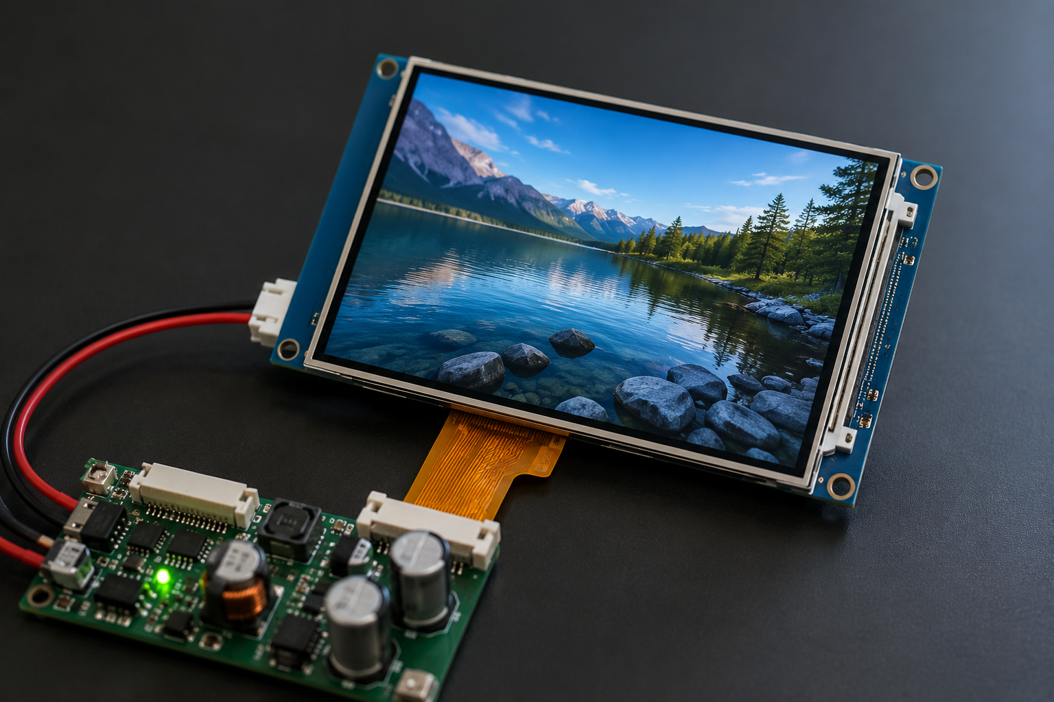
A TFT LCD usually resets when brightness is increased because the backlight draws more power and causes the supply voltage to drop. Other possible causes include regulator current limiting, overheating, LED-driver protection, noise on the reset line, and a firmware watchdog reset.
First confirm whether the processor restarted or only the backlight turned off. Then measure the display input voltage, processor supply, RESET pin, PWM signal, and LED-driver fault output while raising brightness.
Unless otherwise stated, the numbers below are illustrative engineering examples. Always use the electrical limits from the exact TFT module, LED driver, processor, regulator, and capacitor datasheets.
Display size, brightness, interface, and backlight design vary widely. The TFT LCD module collection shows why values from one module should not be copied directly to another.

What Actually Reset?
A dark screen does not always mean that the complete TFT system restarted. Several parts can fail separately:
- Host microcontroller or processor
- TFT controller
- Touch controller
- Backlight LED driver
- Display communication interface
- LCD bias-power circuit
| Visible symptom | Likely fault | First check |
|---|---|---|
| The startup logo appears again | Processor or TFT controller reset | Processor supply, RESET pin, brownout flag, watchdog flag |
| The backlight turns off, but a faint image remains | LED driver or LED-string fault | LED-driver input, enable, fault output, and LED continuity |
| The screen becomes white | Lost initialization, interface data, or LCD bias | Reset timing, interface signals, power sequence, and bias rails |
| The image freezes | Communication or firmware failure | SPI, I²C, RGB, LVDS, MIPI, interrupts, and watchdog status |
| The screen flashes at a fixed interval | Regulator or LED-driver restart protection | Undervoltage, current limit, overvoltage, and temperature |
| Touch stops while the image remains normal | Touch-controller reset | Touch supply, RESET line, interrupt line, and I²C communication |
Use a flashlight when the display goes dark. Shine it across the panel at an angle. If a faint image is still visible, the LCD is still forming an image and the backlight circuit is the main suspect.
If the backlight remains on but no valid image appears, check initialization, interface wiring, controller settings, and FPC connections. See Why Is My TFT LCD Module Not Working? for faults that are not directly caused by the backlight.
Why Brightness Raises Power Use
A TFT LCD uses white LEDs behind the panel. The LEDs are normally connected in one or more series strings. A white LED may have a forward voltage of about 2.8 to 3.3 V, depending on LED type, current, and temperature.
Six LEDs connected in series may therefore need approximately:
6 × 2.8 V = 16.8 V
to:
6 × 3.3 V = 19.8 V
A display powered from 5 V needs a boost converter to generate this higher LED voltage.
Backlight output power can be estimated with:
Backlight power = LED voltage × total LED current
For a backlight operating at 20 V and 80 mA:
20 V × 0.08 A = 1.6 W
If the LED driver is 85% efficient:
1.6 W ÷ 0.85 = 1.88 W input power
At a 5 V input:
1.88 W ÷ 5 V = 376 mA
This is only the backlight current. If the TFT logic uses 150 mA and the processor uses 200 mA, the total average current becomes:
376 mA + 150 mA + 200 mA = 726 mA
A high-brightness display normally needs more backlight power than a standard indoor display of a similar size. For example, this 4.3-inch 900 cd/m² TFT LCD should not be given the same backlight power budget as a lower-brightness module.
Brightness and Input Current
The relationship between a software brightness value and input current is not always linear. The following example shows a small embedded system with a fixed logic load and a PWM-controlled backlight:
| Brightness setting | Example system current | Increase from previous level |
|---|---|---|
| 30% | 360 mA | — |
| 60% | 520 mA | 160 mA |
| 100% | 740 mA | 220 mA |
This table is an example, not a standard current curve. Firmware may apply gamma correction, a lookup table, automatic brightness control, analog current adjustment, or a combination of these methods.
When reading a module specification, confirm whether the stated backlight current means:
- Current for one LED string
- Total current for all LED strings
- Maximum continuous current
- Average current under PWM control
Do not multiply the current by the number of strings if the datasheet already gives the total backlight current.
Input Voltage and Boost Current
A regulated backlight behaves approximately like a constant-power load. If the input voltage falls, the boost converter may draw more current to maintain the required LED power.
The following example assumes:
- LED output power: 1.8 W
- LED-driver efficiency: 85%
- Stable LED-current setting
| Driver input voltage | Estimated input current |
|---|---|
| 5.0 V | 424 mA |
| 4.7 V | 451 mA |
| 4.5 V | 471 mA |
| 4.2 V | 504 mA |
The calculation is:
Input current = LED output power ÷ efficiency ÷ input voltage
This creates a harmful cycle:
- Brightness increases.
- Backlight power increases.
- Cable or regulator voltage drop increases.
- The display input voltage falls.
- The boost converter draws more input current.
- The voltage falls further.
Power Source and Wiring
The first electrical measurement should be the voltage at the display connector. Every part of the supply path has some resistance:
- Power adapter
- Battery
- USB port or hub
- USB cable
- Board connector
- Fuse
- Protection diode or MOSFET
- PCB trace
- Ground-return wire
The steady voltage loss is:
Voltage drop = current × total path resistance
At an 800 mA system load:
| Total positive and ground resistance | Voltage drop | Voltage remaining from a 5 V source |
|---|---|---|
| 0.1 Ω | 0.08 V | 4.92 V |
| 0.3 Ω | 0.24 V | 4.76 V |
| 0.5 Ω | 0.40 V | 4.60 V |
| 0.8 Ω | 0.64 V | 4.36 V |
A 0.8 Ω path is possible with long thin wiring, poor connectors, breadboards, jumper wires, and protection components combined. It is not a normal target for a finished PCB.
Measure the voltage at the source and at the display at the same time:
- If the source stays stable but the display input falls, check the cable, connector, fuse, protection circuit, and PCB path.
- If both voltages fall, check the adapter, battery, USB source, or upstream regulator.
A multimeter may show a normal average voltage while a short drop resets the processor. Use an oscilloscope when the DC reading looks normal but the fault continues.
Brownout Reset
Many processors contain a brownout detector, also called a low-voltage reset circuit. It resets the processor when the supply voltage falls below a set limit.
The exact limit is not universal. One processor may reset near 3.0 V, while another may use a different fixed or programmable level. Use the processor datasheet and actual brownout configuration.
Read the reset-cause register immediately after startup. It may show:
- Power-on reset
- Brownout reset
- External RESET
- Watchdog reset
- Software reset
- Clock fault
Do not disable brownout protection to hide the restart. The processor may then continue running below its safe voltage and produce code errors, memory corruption, or invalid output signals.
Regulator Limits
A regulator can lose control of its output when the TFT and backlight demand more current than it can provide.
Suppose a regulator can deliver 600 mA under the actual PCB and temperature conditions. The system uses 420 mA at low brightness and 680 mA at full brightness. At full brightness, the regulator may enter protection.
| Protection mode | What happens | Visible result |
|---|---|---|
| Current limit | The regulator limits current and its output voltage falls. | Immediate reset or unstable display |
| Foldback limit | The allowed current falls further as the voltage drops. | The board may fail to restart |
| Hiccup protection | The regulator turns off, waits, and tries again. | Regular flashing or restart cycles |
| Thermal shutdown | The regulator turns off after becoming too hot. | Works briefly and then resets |
The current printed on the first page of a regulator datasheet is not always the continuous current available in the finished device. Check:
- Input and output voltage
- Inductor saturation current
- PCB copper area
- Package thermal resistance
- Ambient temperature
- Enclosure airflow
- Switching frequency
- Efficiency at the actual load
If the reset happens immediately after brightness is increased, check voltage drop and current limiting first. If it happens after several seconds or minutes, check the regulator, LED driver, inductor, diode, and MOSFET temperatures.
Linear Regulator Heat
A linear regulator converts the difference between input and output voltage into heat:
Power loss = (input voltage − output voltage) × current
| Input and output | Load current | Regulator heat loss |
|---|---|---|
| 12 V to 5 V | 300 mA | 2.1 W |
| 12 V to 5 V | 500 mA | 3.5 W |
| 12 V to 5 V | 700 mA | 4.9 W |
| 9 V to 5 V | 300 mA | 1.2 W |
| 9 V to 5 V | 500 mA | 2.0 W |
| 9 V to 5 V | 700 mA | 2.8 W |
Several watts of heat are too much for many small regulator packages without a large copper area, heatsink, or another effective thermal path.
When a system is powered from 9 V or 12 V, a switching regulator is often more suitable for the 5 V TFT rail than a small linear regulator operating with a large voltage difference.
Capacitors and Load Changes
When brightness changes quickly, the regulator cannot increase its current instantly. Local capacitors provide part of the extra current until the regulator responds.
A simplified capacitor-only estimate is:
Voltage change = current step × time ÷ capacitance
The following values assume a 300 mA current increase lasting 200 microseconds. They are worst-case capacitor-only calculations, not exact predictions of a real power rail.
| Capacitance | Calculated voltage change |
|---|---|
| 22 µF | 2.73 V |
| 47 µF | 1.28 V |
| 100 µF | 0.60 V |
| 220 µF | 0.27 V |
| 470 µF | 0.13 V |
In the real circuit, the regulator continues to provide some current, so the actual drop may be smaller. The result also depends on capacitor ESR, PCB resistance, and regulator response.
Capacitor ESR
ESR is the small internal resistance of a capacitor. A sudden current change produces an immediate voltage step:
ESR voltage drop = current step × ESR
For a 400 mA current increase:
| Capacitor ESR | Immediate voltage drop |
|---|---|
| 0.02 Ω | 8 mV |
| 0.05 Ω | 20 mV |
| 0.10 Ω | 40 mV |
| 0.20 Ω | 80 mV |
A measured power waveform may show a fast ESR-related step followed by a slower drop as the capacitor discharges.
Do not select a capacitor only by its printed capacitance. Check:
- Effective capacitance at the operating voltage
- DC-bias loss
- ESR
- Ripple-current rating
- Temperature range
- Distance from the load
A ceramic capacitor marked 10 µF may provide much less than 10 µF after DC voltage is applied. Small ceramic capacitors handle fast switching current, while bulk capacitors support slower load changes.
Adding a large capacitor can be useful as a test, but it is not always the final repair. Too much capacitance can create high startup current or prevent some regulators from starting normally.
PWM and Brightness Control
TFT brightness may be controlled by PWM, analog LED-current control, or both.
- PWM control: The LEDs turn on and off quickly. Brightness changes through the on-time.
- Analog control: The driver changes the continuous LED current.
- Hybrid control: The driver combines PWM and LED-current adjustment.
A software value of 20% brightness does not always equal a 20% PWM duty cycle. Firmware may use gamma correction, a lookup table, or automatic brightness control.
With pure PWM control, the LEDs may still receive their full set current during every on-period. Raising the duty cycle increases average power even when peak LED current remains unchanged.
PWM frequency must stay inside the range supported by the exact module or driver. This 7-inch 800 × 480 TFT LCD, for example, specifies PWM brightness control through its ADJ pin.
PWM Pulse Width
| PWM frequency | Duty cycle | Pulse width |
|---|---|---|
| 20 kHz | 50% | 25 µs |
| 20 kHz | 10% | 5 µs |
| 20 kHz | 5% | 2.5 µs |
| 20 kHz | 1% | 0.5 µs |
| 5 kHz | 10% | 20 µs |
| 5 kHz | 5% | 10 µs |
| 5 kHz | 1% | 2 µs |
If the driver requires a minimum on-time longer than the pulse being sent, it may ignore the pulse or produce inaccurate brightness. The minimum time is driver-specific. Do not apply one value to every TFT.
When changing PWM frequency during testing, measure the average LED current or backlight input power. Do not rely only on how bright the display looks because human brightness perception is not linear.
Lowering LED current reduces both power load and switching-noise amplitude. Therefore, a stable result at lower current does not prove that the problem was only insufficient power.
See How to Improve TFT LCD Module Brightness for other brightness factors. Never increase LED current beyond the module or driver rating.
LED Driver Protection
The LED driver may turn off the backlight even when the host processor continues to run.
| Protection | Possible cause | Typical result |
|---|---|---|
| Undervoltage lockout | Driver input voltage is too low | Backlight turns off as the supply falls |
| Overvoltage protection | Open LED string or disconnected backlight | Boost voltage rises and the driver stops |
| Overcurrent protection | Excess switch or inductor current | Driver limits or stops switching |
| Thermal shutdown | Driver becomes too hot | Backlight works briefly and then turns off |
| Shorted-LED detection | One LED string has unusually low voltage | One string or the complete backlight is disabled |
An open LED string is a common example. The driver raises its output voltage while trying to produce the set current. If the string cannot conduct, the voltage may reach the protection limit and the driver shuts down.
An undersized inductor can also cause a fault. When current exceeds its saturation rating, its inductance falls and current rises faster than expected.
Check the inductor for:
- Inductance value
- Saturation-current rating
- RMS-current rating
- DC resistance
- Temperature rise
LED-driver protection normally turns off only the backlight. It causes a complete processor reset only when it also pulls down a shared supply or disturbs a shared ground or RESET signal.
Power and Ground Noise
A boost converter switches current through an inductor at high frequency. Its input current may be smoother than the LED output current, but the circuit still produces switching ripple and electrical noise.
Noise can reach the processor through:
- A shared power rail
- A narrow shared ground path
- A RESET trace near the inductor
- A long PWM trace
- Capacitive coupling from the switching node
- Magnetic coupling from the inductor
Ground is not exactly zero volts at every point on a PCB. Backlight current flowing through a shared ground path creates a small voltage across that path. The processor may then see a lower effective supply voltage or a false RESET pulse.
Measure processor power directly between its VDD and GND pins. Measuring VDD against a distant connector ground may hide local ground movement.
Useful layout improvements include:
- Place LED-driver input and output capacitors close to the driver.
- Keep the boost switching loop small.
- Keep the inductor and switching node away from RESET, clock, touch, and analog traces.
- Avoid narrow ground paths shared by the processor and backlight.
- Keep the switching-node copper area no larger than necessary.
Reset-Line Noise
The processor supply may remain above its brownout limit while the external RESET pin receives a short unwanted low pulse.
Common causes include:
- A long RESET trace
- A RESET trace routed beside the boost inductor
- A weak pull-up resistor
- A noisy reset supervisor
- A programmer connected during normal operation
- The host and display sharing one reset line
A 100 kΩ pull-up is generally easier to disturb than a 10 kΩ pull-up, but 10 kΩ is not a universal solution. The correct value depends on pin leakage, supervisor type, programmer requirements, and the minimum RESET pulse width.
Probe the RESET signal at the processor pin. A clean waveform at the reset supervisor does not prove that the signal remains clean after travelling across the PCB.
Firmware and Watchdog Resets
A brightness change can also cause a software restart. Noise may corrupt a communication transfer or leave a driver waiting forever.
Possible failures include:
- An I²C transfer that never finishes
- Corrupted SPI data
- A repeated interrupt
- A missed display-ready signal
- A driver waiting for a status flag without a timeout
- A watchdog timeout
Store the reset cause and last program state before they are cleared. A useful fault log can contain:
- Reset-cause register
- Last brightness command
- Last PWM duty cycle
- LED-driver fault status
- Last completed software step
- Supply reading from an ADC, if available
A watchdog reset does not always mean software was the original cause. A power or noise event may stop communication first, and the watchdog may perform the final restart later.
How to Measure the Fault
Use an oscilloscope with single-shot capture. Measure at the circuit that is failing, not only at the power adapter.
Useful signals include:
- Power-source output
- Display input voltage
- Processor VDD
- TFT logic supply
- RESET pin
- PWM signal
- Backlight-enable signal
- LED-driver fault output
Useful trigger points include:
- The processor rail falling below its brownout level
- The RESET pin going low
- The LED-driver fault output changing state
- The backlight-enable signal rising
Use enough pre-trigger memory to capture the event before the screen goes dark. The visible restart may happen after the original voltage drop or fault pulse.
Use a short ground spring when measuring fast low-voltage signals. A long probe ground lead adds inductance and can create false ringing.
On most mains-powered bench oscilloscopes, the probe ground clip is connected to protective earth. Connect it only to circuit ground. Do not connect it to the boost switching node, MOSFET drain, or another floating point.
Use a properly rated differential or isolated probe for floating measurements. Never disconnect the oscilloscope protective earth to make the instrument float.
Illustrative Oscilloscope Result
The following is an example of how a real fault record may look. It is not a measurement from every TFT system.
| Test condition | 5 V rail minimum | 3.3 V rail minimum | Result |
|---|---|---|---|
| 50% brightness | 4.86 V | 3.25 V | Stable |
| 100% brightness, long cable | 4.31 V | 2.92 V | Brownout reset recorded |
| 100% brightness, short low-resistance cable | 4.72 V | 3.21 V | No reset |
In this example, the processor brownout threshold is assumed to be configured near 3.0 V. The 2.92 V minimum explains why it reset. A different processor may use a different threshold.
Test in This Order
- Confirm what failed. Use the startup logo, flashlight test, reset flags, and other working functions.
- Find the brightness threshold. Record PWM duty cycle, frequency, LED current, voltage, current, and temperature.
- Use a stronger source. Connect a regulated supply with short, low-resistance wires.
- Remove weak wiring. Bypass breadboards, thin jumpers, long USB cables, and loose connectors.
- Test local capacitance. Add a suitable temporary bulk capacitor near the display input.
- Lower LED current. Keep PWM at 100% and reduce the programmed current.
- Change PWM frequency. Stay within the driver limits and keep measured backlight power similar.
- Separate backlight power. Keep grounding and signal wiring controlled.
- Check temperature. Test inside the final enclosure at the highest expected ambient temperature.
| Test result | Most useful next check |
|---|---|
| A stronger supply fixes the reset | Original adapter, battery, USB source, or upstream regulator |
| A shorter cable fixes the reset | Cable, connector, fuse, diode, or PCB path resistance |
| Added capacitance fixes the reset | Regulator response, effective capacitance, ESR, and placement |
| Lower LED current fixes the reset | Power limit, heat, inductor stress, ground movement, or noise |
| Changing PWM frequency moves the fault point | Minimum pulse width, driver mode, or noise coupling |
| Power rails stay stable, but RESET goes low | RESET routing, pull-up, supervisor, and ground path |
| Power and RESET stay stable, but watchdog is recorded | Firmware timeouts, communication errors, or interrupts |
Power Budget Example
Consider an example 7-inch TFT system with:
- 5 V source
- TFT logic current: 160 mA
- Processor and memory current: 230 mA
- LED output: 19 V at 100 mA
- LED-driver efficiency: 84%
- Cable-loop resistance: 0.3 Ω
- Local regulator limit: 850 mA
LED output power:
19 V × 0.1 A = 1.9 W
Backlight input power:
1.9 W ÷ 0.84 ≈ 2.26 W
Backlight current at exactly 5 V:
2.26 W ÷ 5 V ≈ 452 mA
Other loads:
160 mA + 230 mA = 390 mA
First total estimate:
452 mA + 390 mA = 842 mA
This is already close to the 850 mA regulator limit. The cable then lowers the display voltage, so the boost driver draws more current to maintain the LED power.
Assuming the source remains at 5 V, cable resistance stays at 0.3 Ω, efficiency remains 84%, and LED output remains 1.9 W, the approximate operating point is:
- Display input voltage: 4.74 V
- Backlight input current: 477 mA
- Total current: 867 mA
- Cable voltage drop: 0.26 V
The corrected current is above the 850 mA regulator limit before startup peaks are included. A larger wall adapter alone will not solve the problem if the local regulator and cable remain undersized.
For battery-operated products, use the lowest battery voltage and the lowest expected converter efficiency. See How to Reduce Display Module Power Consumption for backlight and battery-load considerations.
Power Sequence
Enabling the backlight at full brightness before the logic rails are stable can create a large startup load.
A general startup order is:
- Apply and stabilize the logic power rails.
- Release the processor and TFT RESET signals.
- Send the required display initialization commands.
- Start valid display data.
- Enable the backlight.
- Raise brightness in controlled steps.
The correct order and delays depend on the module. Check the module datasheet rather than using one sequence for every TFT. The guide on how to read a TFT LCD module datasheet explains where to find power, RESET, timing, and initialization requirements.
A brightness ramp lasting several tens of milliseconds may reduce the startup dip. It cannot repair a continuous overload. If the supply cannot support full brightness, a slower ramp only delays the reset.
Fix the Confirmed Cause
| Confirmed cause | Practical repair |
|---|---|
| Continuous voltage loss | Use a stronger source, thicker cable, better connector, wider PCB path, or lower-loss protection circuit. |
| Short voltage dip | Improve local capacitance, regulator response, capacitor ESR, and capacitor placement. |
| Regulator current limit | Use a regulator and inductor rated for the measured worst-case current. |
| Regulator overheating | Reduce power loss, improve efficiency, add copper area, or improve cooling. |
| Inductor saturation | Use an inductor with higher saturation and RMS-current ratings. |
| LED-driver protection | Check LED strings, connector continuity, LED current, boost voltage, and fault status. |
| RESET-line noise | Improve routing, use the correct pull-up, and remove shared noisy ground paths. |
| PWM timing problem | Use a supported frequency and meet the minimum high- and low-pulse times. |
| Watchdog reset | Add communication timeouts, record error states, and remove blocking code. |
If a standard TFT cannot meet the required brightness, power, connector, FPC, touch, or thermal limits, consider a custom TFT LCD module rather than operating a standard part outside its rating.
Example Repair Comparison
The following table shows an illustrative repair result after replacing a high-resistance cable, improving local capacitance, and correcting the power return path:
| Measurement | Before repair | After repair |
|---|---|---|
| Maximum-brightness input current | 820 mA | 790 mA |
| Display input minimum | 4.28 V | 4.76 V |
| 3.3 V rail minimum | 2.88 V | 3.24 V |
| Power-path resistance | 0.55 Ω | 0.16 Ω |
| RESET low pulse | 1.2 µs detected | Not detected |
| Full-brightness test | Reset after 3–8 minutes | 4 hours without a reset |
These figures show the type of before-and-after evidence that should be collected. They are not guaranteed results for every board.
Avoid These Fixes
- Do not disable brownout protection. It may allow the processor to run at an unsafe voltage.
- Do not raise the supply above the TFT rating. It may damage the display controller or LED driver.
- Do not add a very large capacitor without checking startup current. It can create a new startup fault.
- Do not change several parts at once. You will not know which change fixed the problem.
- Do not measure only at the adapter. The important voltage is at the display and processor pins.
- Do not replace the TFT first. Test the module on a known-good board before blaming the panel.
Production Validation
After the repair, test the display under the worst expected conditions:
- Maximum backlight brightness
- Minimum allowed input voltage
- Highest operating temperature
- CPU at high load
- Wireless transmitter active
- Other high-current loads active
- Longest approved power cable
- Cold startup
- Hot restart
- Repeated brightness changes
- Continuous full-brightness operation
- Several production samples
Confirm that the processor rail stays above its safe level, the RESET pin remains stable, the regulator does not enter protection, and the LED driver runs without overheating or reporting a fault.
Technical References
- Texas Instruments: TPS61196 WLED Driver Datasheet
- Microchip: Brown-Out Reset Operation
- Murata: Ceramic Capacitor DC-Bias Characteristics
- Tektronix: Oscilloscope Probe Grounding and Measurement Safety
Conclusion
A TFT LCD usually resets at higher brightness because the added backlight load causes voltage loss, regulator protection, overheating, or noise on the power and RESET lines. First identify whether the processor restarted or only the backlight stopped. Then measure the display input, processor VDD, RESET pin, PWM signal, and driver fault output. In the power-budget example, cable loss raised the calculated load from 842 mA to 867 mA, exceeding an 850 mA regulator limit. Test with a stronger source, shorter wiring, correct capacitance, safe PWM timing, and proper grounding before replacing the display.
Leave a comment
This site is protected by hCaptcha and the hCaptcha Privacy Policy and Terms of Service apply.