



Yes, an HDMI source can drive an LVDS panel through a compatible active HDMI-to-LVDS controller board. It cannot drive the panel through a passive cable or direct pin connection. The board must convert the video signal and supply the correct LVDS timing and mapping. Panel power and backlight requirements must also be met, either by the board or by suitable separate circuitry. TI documents one conversion path using a DVI-compatible receiver followed by an LVDS transmitter [1].
Choose by exact panel model and revision, not just resolution or connector size. A “1080p HDMI to LVDS” label does not establish compatibility with your particular panel.
Why a passive HDMI to LVDS cable will not work
The signals are different. The TMDS input in TI's bridge example has three data pairs and a clock pair; the LVDS output uses different serialization and pin mapping. A passive cable cannot perform that conversion [1]. The HDMI protocol overview and LVDS interface overview explain the two sides.
Do not connect pins by name or assume HDMI power can supply the panel and backlight. Obtain the required rails, current capability, and startup sequence from the panel and controller documentation.
What an HDMI-to-LVDS board does
TI's example follows this path: HDMI/DVI source → DVI-compatible TMDS receiver → parallel RGB and timing signals → LVDS transmitter → panel [1]. This is one implementation, not a specification for every commercial controller.
You need HDMI input and LVDS output. A reverse-direction converter is not interchangeable. An HDMI-to-MIPI adapter targets a different panel interface. The display-interface selection guide helps distinguish the interfaces; the panel datasheet determines which one you need.
The receiver limit is not the board's guaranteed capability
The TI TFP401 receiver supports a pixel rate up to 165 MHz. That is a receiver limit, not a universal HDMI-to-LVDS limit or a guarantee that a board supports every mode below it [2]. The complete path must also support the required transmitter clock, output channels, panel timing, and configuration.
For comparison, TI's SN75LVDS83B is a 10- to 135-MHz LVDS transmitter/serializer, not an HDMI receiver or a complete converter [6]. Its clock range must be checked separately. A receiver's pixel rate and a dual-channel LVDS clock do not necessarily describe the same point in the signal chain [1][2].
Input restrictions depend on the design
TI's referenced two-chip design requires DVI-compliant TMDS input without HDMI data islands, including audio, or deep color above 24 color bits [1]. For that path, select a supported RGB mode and disable incompatible output formats. Other controller boards require their own format checks. HDMI's broader audio/video feature set does not establish what an individual bridge accepts [4].
How to match a board to your LVDS panel
Compare the full panel model and revision with the controller's supported-panel list, configuration, and cable pinout. An exact listed match is useful evidence. An unlisted panel needs confirmation of all relevant parameters, not just a similar resolution.
| Check | Required match | Insufficient evidence |
|---|---|---|
| Channel mode | The panel's single- or dual-channel arrangement matches the board output. | The same connector pin count. |
| Color format | Color depth, JEIDA/VESA mapping, and signal assignments match. | Both products being labeled LVDS. |
| Timing | Output clock, active area, blanking, sync, and DE behavior meet the panel specification. | The same active resolution alone. |
| Power and backlight | Correct rails, current capability, sequencing, enable, and dimming are provided. | A board having a power connector. |
| Cable | Pinout, orientation, grounding, and cable specification match both ends. | A plug that physically fits. |
| Configuration | Firmware, jumpers, or register settings support the intended panel and input mode. | A generic “1080p compatible” label. |
Single-channel and dual-channel LVDS
TI describes single-channel LVDS/OLDI with three data pairs for 18-bit color or four for 24-bit color; dual-channel uses six or eight data pairs, respectively. Clock pairs are additional. Its resolution ranges describe typical applications, not a rule that overrides the panel datasheet [1].
The report lists 1280 × 800 and 720p as typical single-channel applications with a 70–75 MHz clock, and 1080p as a typical dual-channel application with a 74.25 MHz clock [1]. The latter figure belongs to that dual-channel arrangement. Do not use it as the HDMI source pixel-clock setting merely because the panel is 1080p.
Mapping and timing
Match the documented JEIDA/VESA mapping and color depth; TI provides mapping examples for the conversion path [1]. A mapping mismatch can produce incorrect colors. Read the complete timing table rather than relying on active resolution alone.
The RGB888 timing explanation gives background, but does not replace panel-specific blanking, polarity, or DE requirements. Use a mode and refresh rate supported by the complete path; 60 Hz is not a universal startup requirement.
Panel power and backlight
LVDS data pairs carry signals, not the panel's operating power. Verify logic rails and backlight supply separately. A converter may need external panel-power circuitry or a backlight driver; do not assume these are included. The distinction between a controller board and display driver IC helps identify which functions a product actually provides.
Check sequencing and enable/dimming requirements before applying power. Never infer a panel voltage from a connector or another panel of the same size.
Why firmware and EDID matter
On configurable controllers, firmware or hardware settings may select panel timing, channel mode, mapping, and power behavior. Ask which configuration is supplied. The panel-control-board selection guide provides context; not every simple bridge has firmware that can correct a mismatch.
EDID describes display capabilities to the source; VESA maintains E-EDID and DisplayID standards [5]. Check what the controller advertises and accepts. EDID does not itself guarantee correct downstream wiring, mapping, or power. Do not assume a basic receiver/transmitter bridge can scale an arbitrary input resolution to the panel's native timing.
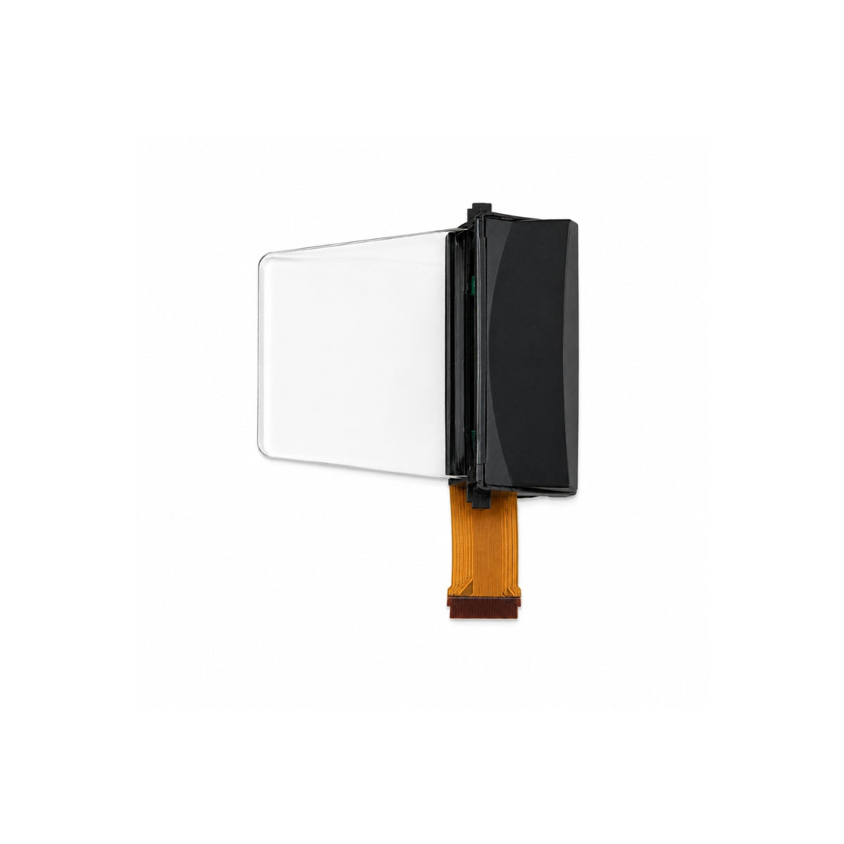
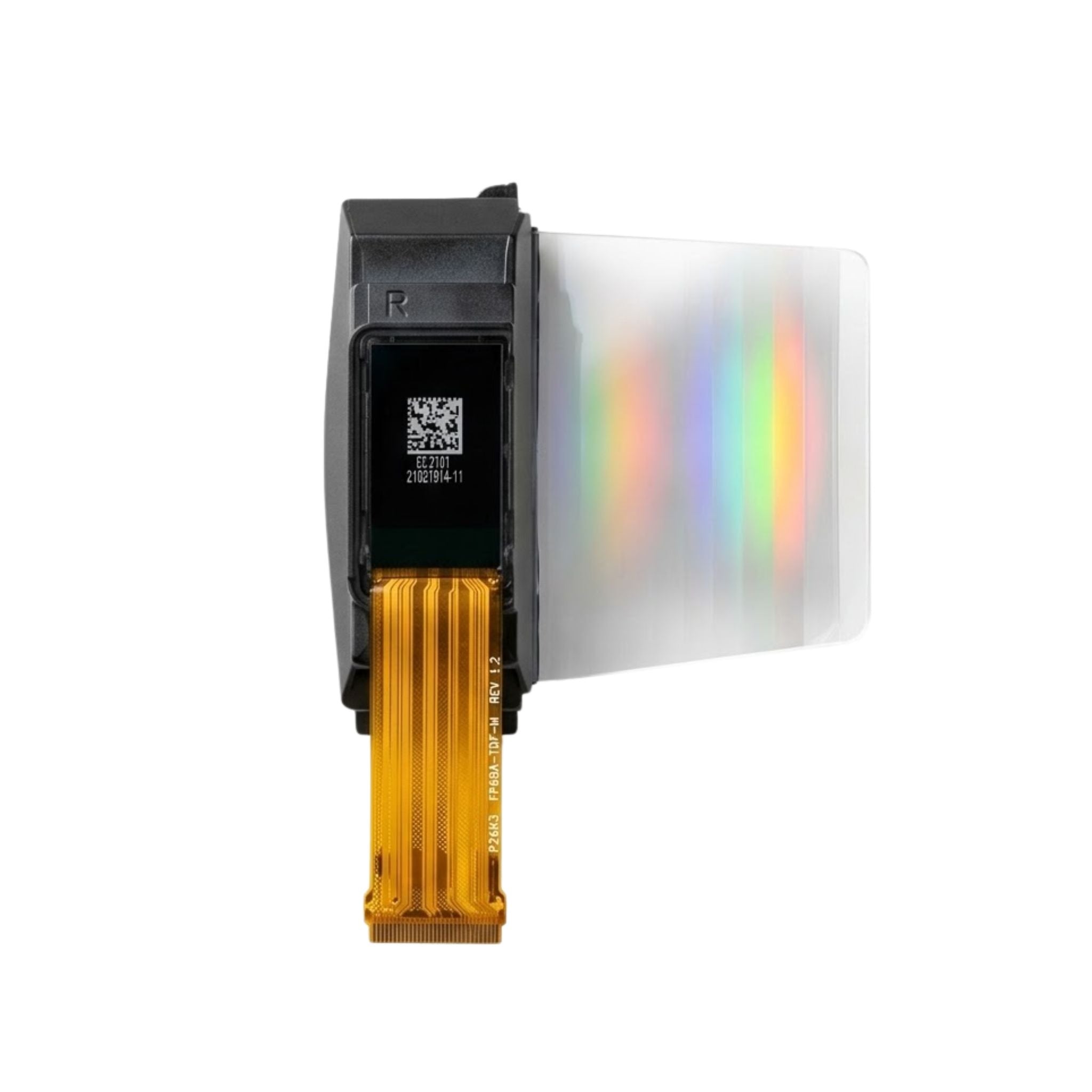
The HDMI-to-LVDS adapter product page illustrates a product tied to a specified compatible display module rather than universal panel support. When comparing the adapter families, check interface direction and documented compatibility first.
A documented setup workflow
TI's published bridge design supplies a concrete starting point for implementation checks [1]. Apply it to the actual panel and board documentation as follows.
- Identify the full panel model and revision. Obtain its datasheet; the datasheet-reading guide helps locate pinout, timing, and initialization requirements.
- Compare every item in the compatibility table. Use the display-adapter selection guide for interface distinctions, then confirm the exact board, configuration, and cable with its supplier.
- With power disconnected, verify cable orientation, pin assignments, required rails, backlight circuitry, and settings. Resolve unknown values before energizing the assembly.
- Select an input mode explicitly supported by the controller and panel path. For the TI DVI-compatible example, observe its input-format restrictions [1].
- Record the source mode, controller configuration, cable, and observed symptoms. Change one variable at a time; disconnect power before wiring changes.
What the TI design guidance actually applies to
For the receiver-to-transmitter parallel connection, TI specifies matching data and control signals within 400 mils of the reference clock trace and a maximum distance of 6 inches. It also specifies compatible clock edges and 3.3 V IOVCC for the listed SN65LVDS93A/B variants [1]. These are design-specific inter-device guidelines, not a six-inch limit for every panel-side LVDS cable.
Nominal LVDS signaling uses about 3.5 mA through a 100-ohm termination, producing about 350 mV differential voltage [3]. That signal voltage is not a panel supply voltage. Use the actual transmitter, receiver, board, and cable specifications when implementing the connection.
What to check if the screen stays black
A black screen alone does not identify a failed part. Separate power, input, and output checks rather than repeatedly buying adapters.
- Power and backlight: verify documented supplies and enable conditions using appropriate measurements. A lit backlight does not prove the video path is correct.
- HDMI input: compare the source's actual resolution, refresh rate, and color format with the controller's accepted modes and EDID.
- LVDS output: verify channel mode, mapping, output timing, cable orientation, and panel configuration.
- Protected content: check documented HDCP support. TI's receiver table distinguishes devices with and without it; an HDMI connector alone is not proof [1].
Record each result before changing the next setting. Incorrect colors warrant checking mapping and color settings; unstable pictures also warrant checking timing and cable integrity. These symptoms guide investigation, but do not prove a single cause.
HDMI to LVDS questions
Will any 1080p controller work with any 1080p LVDS panel?
No. Resolution alone does not establish matching channels, mapping, timing, power, configuration, or cable pinout. Confirm the full panel model and revision.
Can this conversion support 1080p at 120 Hz?
Not through the arrangement described in TI's application report, which excludes that application [1]. Other designs need their own documented input bandwidth, output interface, and panel support. A newer HDMI source does not upgrade an older bridge.
Does LVDS carry the HDMI audio?
The panel video link in the referenced design does not deliver HDMI audio, and the design requires input without HDMI audio data islands [1]. If sound is required, check for a separately supported audio path on the controller.
Does the board need to list my exact panel?
An exact model and revision match is the clearest starting point. An unlisted panel may still be usable if the supplier confirms all electrical, timing, mapping, power, and configuration requirements. A shared connector or resolution is not that confirmation.
Before you order
For a working HDMI-to-LVDS connection, match the panel, controller configuration, input mode, cable, and power/backlight arrangement as one system. Buy a documented conversion path, not a cable that merely fits.
Not sure your panel matches?
Send the panel model, revision, datasheet, and target source mode to request a compatibility assessment.
Get a Compatibility QuoteReferences
[1] Texas Instruments, How to Bridge HDMI/DVI to LVDS/OLDI, SLLA325C, sections 1–6 and mapping examples. Accessed 2026-10-28; PDF text rechecked 2026-11-06. Applies to the documented design, its typical channel/clock examples, input restrictions, HDCP table, and inter-device layout rules—not every controller board.
[2] Texas Instruments, TFP401 TMDS DVI receiver. Accessed 2026-10-28; rechecked 2026-11-06. Supports the receiver's 165-MHz pixel-rate capability, not a guaranteed complete-board limit.
[3] Texas Instruments, LVDS Owner's Manual, SNLA187. Accessed 2026-10-28; URL rechecked 2026-11-06. Supports nominal LVDS current, termination, and differential swing, not panel power requirements.
[4] HDMI Licensing Administrator, HDMI specification overview. Accessed 2026-10-28; rechecked 2026-11-06. General audio/video specification context; individual bridge capabilities require separate documentation.
[5] VESA, Free Standards including E-EDID and DisplayID. Accessed 2026-10-28. Supports display-identification standards context, not any board's configured EDID or compatibility.
[6] Texas Instruments, SN75LVDS83B product information and datasheet. Accessed 2026-11-06. Applies to this 10- to 135-MHz LVDS transmitter/serializer example, not an HDMI receiver or complete converter.
Hinterlasse einen Kommentar
Diese Website ist durch hCaptcha geschützt und es gelten die allgemeinen Geschäftsbedingungen und Datenschutzbestimmungen von hCaptcha.