


Introduction to HDMI Protocol
Overview
HDMI (High-Definition Multimedia Interface) is a standardized protocol for transmitting high-quality digital audio and video signals between devices. It was first introduced in 2002 and has since become the most widely used method for connecting devices such as TVs, monitors, and gaming consoles to other devices like laptops and DVD players. HDMI cables can transmit both uncompressed and compressed audio and video signals, making it a versatile and reliable option for home entertainment setups.The transport is based on the Transition Minimized Differential Signaling (TMDS) protocol.
Physical structure
The physical structure of an HDMI cable consists of 19 pins that are arranged in three rows. The first row contains five pins, the second row contains four pins, and the third row contains ten pins. These pins are responsible for transmitting the different types of signals, including audio, video, and control signals. The HDMI cable also includes a sturdy connector and a durable outer jacket to protect the internal wires from damage.

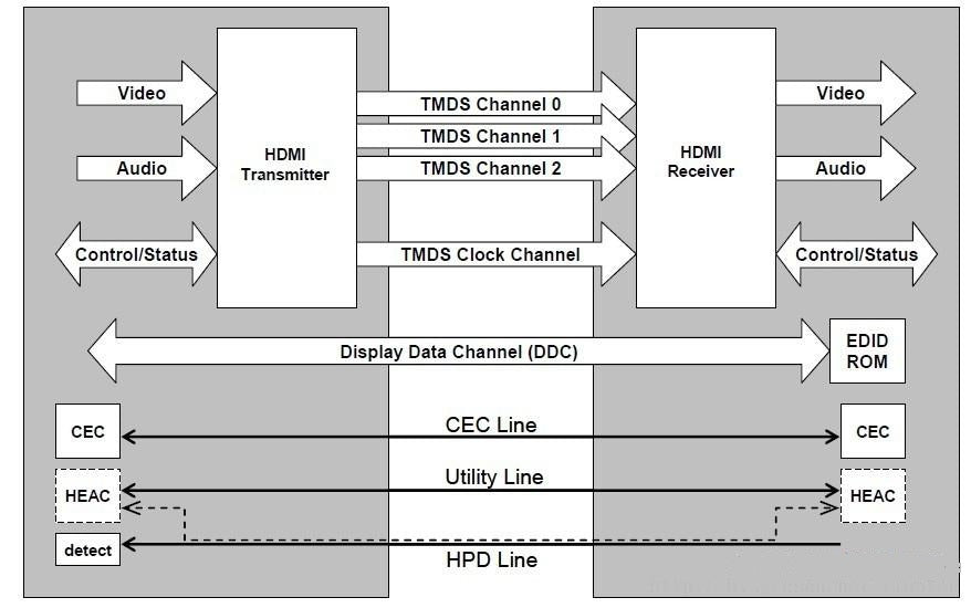
The above figure is the HDMI block structure diagram, it can be seen that HDMI is used for the connection between audiovisual source and sink, HDMI cable by 3 groups of differential signals to transmit TMDS data, 1 group of differential signals to transmit clock. In addition, HDMI has a channel for DDC to connect to the sink's EDID. CEC and HEAC are both optional protocols for HDMI.

HDMI defines five types of connector, with type A being the most common.
- 1-9 are the pins used for TMDS data transmission, there are three groups;
- 10-12 are the pins used for TMDS clock transmission, and there is a set of them. TMDS clock is pixel clock;
- 13 is the CEC pin, a consumer electronics compatible transport protocol;
- 14 is the reserved pin;
- 15,16 are the pins of DDC, DDC is based on I2C protocol transmission, so the pins are SCL and SDA;
- 17 is ground;
- 18 is +5V power;
- 19 is the HPD pin, which is used to establish the connection.
transmission
Overview
HDMI transmission consists of three sets of TMDS channels and one set of TMDS clock channels, which operate at the pixel frequency of the video signal, and at each cycle, each TMDS data channel sends 10bit data.

The above figure is a diagram of HDMI transmission. As can be seen from the figure, HDMI transmission of the following four types of data:
- The Preamble control information, CTLx in the figure, can be used to indicate whether data island or video data will be transmitted later. D[1:0] transmission via channel1 and 2, occupying 4 bits.
- Data Island ,is a packet of data, such as the Audio packet. D[3:0] over three channels, 12 bits.
- Video Data, RGB format images are transmitted in the diagram. R,G, B are transmitted through channel2,1, and 0 respectively, with 8bit for each color and 24bit in total.
- HSYNC, VSYNC. A D[1:0] transmission using channel0 takes 2 bits.
The 8bit data in the source passes through the TMDS encoder to get 10bit data, and then passes through the serializer to output serially. At the sink, 10bit data is restored first, and then 8bit source data is obtained by TMDS decoder.
In addition, HDMI video is stream transmission, and does not involve packet transmission.

The above figure is the hdmi timing diagram for transmitting 720x480p video.
-
During the video data period, valid video data is transmitted.
The video data period begins with a leading gurad band of 2 characters (pixel) in length, and the guard band is as follows:
- ch0: q_out[9:0] = 0b1011001100
- ch1: q_out[9:0] = 0b0100110011
- ch2: q_out[9:0] = 0b1011001100
The transition process of the three transmission stages is shown in the following figure:

-
During the data island period, audio and auxiliary data are transmitted in the form of packets.
The data island period transmits audio data and auxiliary data, which includes infoframes and other data used for the description of audio and video information. The data island period starts with a leading guard band of 2 characters in length and ends with a trailing guard band of 2 characters in width. The guard band is as follows:
- ch0: q_out[9:0] = n.a
- ch1: q_out[9:0] = 0b0100110011
- ch2: q_out[9:0] = 0b0100110011
-
During the control period, CTLx and HSYNC, SYNC transmit.
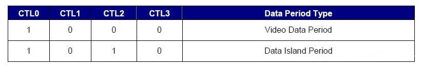
There are only two types of preamble information combinations, CTL0:3=1000 for video data period to follow, and CTL0:3=1010 for data island period to follow. HSYNC, VSYNC are also subject to change at this time.
Both the data island period and the control period are conducted in the blanked area. In the figure, line blanking occupies 138 pixels and field blanking occupies 45 rows.
Video
Three pixel encodings are supported: RGB4:4:4, YCbCr4:4, YCbCr4:2:2
video format In addition to the CEA-861-D format, a number of more specialized formats will be supported
color depth can support 24, 30, 36 and 48bits per pixel
Below is the pixel encoding diagram of 24bit/pixel RGB444, YCbCr422, YCbCr444 respectively. RGB444 takes 8 bits per color, Y takes 12 bits in YCbCr422,C takes 12 bits, and Y,Cb, and Cr all take 8 bits in YCbCr444.


Deep Color mode
- 24 bit mode: 1 pixel/group, 1 fragment/group
- 30 bit mode: 4 pixel/group, 5 fragment/group
- 36 bit mode: 2 pixel/group, 3 fragment/group
- 48 bit mode: 1 pixel/group, 2 fragment/group
Control
InfoFrame
Infoframes are transmitted as Infoframe packets, which are no more than 30 bytes in size plus a checksum byte. The format and content of infoframe should be checked in spec.
AVI(Auxiliary Video Information) Infoframe
Audio Infoframe
HDMI Vendor Specific Infoframe, required to send this packet when transmitting 4kx2k or 3D format
EDID & DDC
The sink device stores EDID information in ROM, and the source will read the EDID through the DDC channel to get the attributes of the display device after receiving the HPD. EDID consists of two parts, the first 128 bytes conforming to the EDID1.3 data structure and the 128-byte extended EDID conforming to the CEA extension verison3.
Read more

Field of View (FOV) determines how much virtual content AR glasses display—consumer models hit 30-50°, premium reach 70°+. Wider FOV lets users see navigation cues or alerts without turning, enhanc...
HDMI interface is the most common interface of hardware equipment, including projector, TV, box, player and so on a variety of hardware devices, are necessary HDMI interface. The HDMI interface is ...
3 comments
kys
Vladimir Putin
kys
Vladimir Putin
1. How secure is HDMI data transmission?
2. Is it a two-way or one-way data transmission?
3. When a PC feeds a video HDMI signal to a TV, is there a risk of unauthorized access to the PC from any unused HDMI port or other TV ports?
Md Mokammel Hoque
Leave a comment
This site is protected by hCaptcha and the hCaptcha Privacy Policy and Terms of Service apply.