









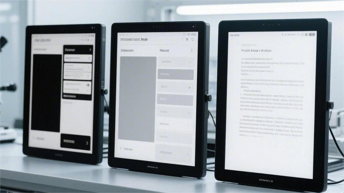
Quick answer: An ePaper BUSY pin timeout means the firmware waited for the display controller to finish an operation, but the expected idle level was not detected before the timeout ended. Common causes include a wrong GPIO, reversed BUSY polarity, unstable power, failed reset, SPI errors, an incorrect display driver, or an incomplete wake-up sequence.
Do not replace the screen or increase the timeout immediately. First find the stage where the timeout occurs, read the raw BUSY level, measure the supply voltage during refresh, and confirm that the firmware matches the exact panel and controller.

BUSY Pin Basics
The BUSY pin tells the microcontroller whether the ePaper controller is still processing an operation. It is normally an output from the display and must be configured as an input on the microcontroller.
| Pin | Purpose |
|---|---|
| VCC | Powers the display module |
| GND | Provides a common ground |
| DIN or MOSI | Sends commands and image data |
| CLK or SCK | Provides the SPI clock |
| CS | Selects the display controller |
| DC | Selects command or data mode |
| RST | Resets the display controller |
| BUSY | Shows whether the controller is working |
Some adapter boards also have a PWR or EN pin. If this pin is not enabled, the SPI pins may still change while the display controller remains unpowered.
BUSY polarity is panel-specific. Some controllers are busy when the pin is HIGH, while others are busy when it is LOW. For example, the 1.54-inch 200 × 200 ePaper display specifies that BUSY is HIGH while the controller is processing an operation.
pinMode(EPD_BUSY_PIN, INPUT);

while (digitalRead(EPD_BUSY_PIN) == BUSY_ACTIVE_LEVEL) {
    // The display controller is still working.
}
Do not copy the BUSY level from a display that only has a similar size or resolution. Check the exact product page, datasheet or driver configuration.
Useful Reference Data
ePaper specifications vary widely. The following two products show why one power range, SPI speed or timeout cannot be used for every display.
| Parameter | 1.54-inch, 200 × 200 | 3.5-inch, 240 × 360 |
|---|---|---|
| Logic supply | 2.2–3.7 V, 3.0 V typical | 2.8–3.6 V, 3.0 V typical |
| Refresh time | 3 seconds | 750 ms full refresh at 25°C |
| Partial refresh | Check the selected driver and waveform | 250 ms at 25°C |
| Maximum SPI clock | 20 MHz | 4 MHz |
| Typical active power or current | 4.5 mW | 10 mA at 3.0 V |
| Deep-sleep value | 0.003 mW | 1 μA |
| Operating temperature | 0–50°C | 0–35°C |
| BUSY level | HIGH during operation | Use the exact product documentation |
These figures are product examples, not universal ePaper limits. Browse the ePaper display collection and check the page for the exact model before setting voltage, clock speed or timeout values.
Find the Timeout Stage
Print a message before every function that may wait for BUSY. The final message shows the stage where the firmware stopped.
Serial.println("EPD: reset");
epdReset();

Serial.println("EPD: initialize");
epdInit();

Serial.println("EPD: power on");
epdPowerOn();

Serial.println("EPD: write image");
epdWriteImage();

Serial.println("EPD: refresh");
epdRefresh();

Serial.println("EPD: power off");
epdPowerOff();
The final printed stage does not always show where the original error occurred. A bad initialization command, for example, may only become visible when the firmware later waits for a refresh to finish.
| Timeout stage | Check first |
|---|---|
| First BUSY check | GPIO number, BUSY wire, polarity, power and ground |
| After reset | RST wiring, reset level, startup delay and power-enable pin |
| During initialization | Controller driver, SPI mode, CS and DC timing |
| After power-on | Power stability, command sequence and controller match |
| During full refresh | Supply voltage, update command, driver and timeout |
| During partial refresh | Partial mode support, update window and waveform table |
| After deep sleep | Hardware reset and complete reinitialization |
Check the BUSY GPIO and Voltage
Read the raw BUSY value before and after hardware reset.
Serial.print("BUSY before reset: ");
Serial.println(digitalRead(EPD_BUSY_PIN));

epdReset();

Serial.print("BUSY after reset: ");
Serial.println(digitalRead(EPD_BUSY_PIN));
If the value never changes, check these items:
- The BUSY wire is connected to the correct display pin.
- The GPIO number matches the physical MCU pin.
- The GPIO is configured as an input.
- The display and MCU share the same ground.
- The display is receiving power.
- The configured BUSY polarity matches the panel.
- No unwanted pull-up or pull-down is holding the line.
On a 3.3 V system, a reading close to 0 V normally represents LOW, while a reading close to 3.3 V normally represents HIGH. A voltage that stays near the middle of the supply range can indicate a floating pin, poor connection or level-shifting problem.
Use the input thresholds from the exact panel when available. As one example, the 1.54-inch model above specifies LOW at no more than 0.2 × VCI and HIGH at no less than 0.8 × VCI. With a 3.0 V supply, that means no more than 0.6 V for LOW and at least 2.4 V for HIGH.
Check the Power Supply
An ePaper panel uses almost no power to hold a static image, but the controller needs more power while generating the refresh waveform. A weak regulator, long wire or poor connector may work during startup and fail during refresh.
- Measure VCC while the screen is refreshing, not only while it is idle.
- Keep power and ground wires short.
- Check breadboard contacts and connectors.
- Make sure any
PWRorENpin is active. - Use the capacitors shown in the module circuit or datasheet.
- Do not power the display through MOSI, SCK or other signal pins while VCC is off.
The 3.5-inch 240 × 360 ePaper display uses a 2.8–3.6 V logic supply and lists 10 mA as its typical operating current at 3.0 V. Its product notes also give a 1 μF X5R or X7R capacitor rated for 25 V as a local decoupling example.
Do not select a power supply that can provide only the listed typical current. The regulator must also handle short current changes when the internal display voltages start.
For more background on active, standby and deep-sleep power, see the low-power display guide .
Check the Hardware Reset
A reset must use the correct active level, pulse width and startup delay. These values depend on the controller, so a delay copied from another display may not work.
Confirm that:
- RST is configured as an output.
- The active reset level is correct.
- The reset pulse meets the controller specification.
- The power supply is stable before reset is released.
- The firmware waits before sending the first SPI command.
- The display is reset again after deep sleep when required.
If the board has a power-enable pin, enable power first, wait for the supply to stabilize, and then reset the controller.
Check SPI Communication
If BUSY changes after reset but becomes stuck after initialization or power-on, the display may not be receiving the correct SPI commands.
- Confirm MOSI, SCK, CS and DC wiring.
- Use the SPI mode required by the controller.
- Set DC before pulling CS LOW.
- Keep CS LOW for the complete transfer.
- Check whether another device uses the same CS pin.
- Confirm that the MCU logic voltage is compatible with the display.
void sendCommand(uint8_t command) {
    digitalWrite(EPD_DC_PIN, LOW);
    digitalWrite(EPD_CS_PIN, LOW);
    SPI.transfer(command);
    digitalWrite(EPD_CS_PIN, HIGH);
}

void sendData(uint8_t data) {
    digitalWrite(EPD_DC_PIN, HIGH);
    digitalWrite(EPD_CS_PIN, LOW);
    SPI.transfer(data);
    digitalWrite(EPD_CS_PIN, HIGH);
}
Maximum SPI speed also differs by model. The 1.54-inch example supports up to 20 MHz, while the 3.5-inch example supports up to 4 MHz. During troubleshooting, start at 500 kHz or 1 MHz, especially when using jumper wires or a breadboard. Raise the speed only after the display works reliably.
Read the SPI bus guide for more information about MOSI, SCLK, CS and SPI modes.
Make Sure the Driver Matches the Display
The same screen size and resolution do not guarantee the same controller. Similar panels may use different commands, BUSY polarity, memory layout, waveform tables and sleep sequences.
Confirm the following before changing the timeout:
- Full product model
- Controller IC
- Resolution and color type
- BUSY active level
- SPI mode and maximum clock
- Full and partial refresh support
- Required reset and wake-up sequence
A wrong driver may still send valid-looking SPI data, but the controller may ignore the commands or remain busy because the update sequence is not supported.
Set a Safe BUSY Timeout
Never wait for BUSY in an endless loop. A disconnected wire or failed controller could freeze the whole application.
bool epdWaitUntilIdle(uint32_t timeoutMs) {
    uint32_t startTime = millis();

    while (digitalRead(EPD_BUSY_PIN) == BUSY_ACTIVE_LEVEL) {
        if ((uint32_t)(millis() - startTime) >= timeoutMs) {
            Serial.println("EPD BUSY timeout");
            return false;
        }

        delay(1);
    }

    return true;
}
Use the panel specification as the starting point. During initial testing, a timeout of about twice the listed maximum operation time gives a practical safety margin.
| Listed operation time | Initial debugging timeout |
|---|---|
| 250 ms | 500–1000 ms |
| 750 ms | 1500–2000 ms |
| 3 seconds | About 6 seconds |
| Unknown | Use a conservative limit and measure the real BUSY time |
These are debugging starting points, not product specifications. A longer timeout cannot repair a wrong GPIO, reversed polarity, missing power or incompatible driver.
Check Temperature and Refresh Time
Refresh time depends on temperature. Charged particles move more slowly near the lower end of the panel’s operating range, so BUSY may remain active longer than it does at room temperature.
The 3.5-inch product lists 750 ms full refresh and 250 ms partial refresh at 25°C, with an operating range of 0–35°C. The 1.54-inch product lists a 3-second image update and an operating range of 0–50°C.
If the display works at 25°C but times out in a cold room, check the supported temperature range and temperature-dependent waveform before changing the hardware.
Understand Partial Refresh Problems
Missing previous-frame data usually causes ghosting, wrong pixels or a bad first partial update. It does not normally keep BUSY active forever.
A partial-refresh timeout is more likely to come from:
- A panel that does not support the selected partial mode
- An incorrect partial-update command
- An invalid update window
- A waveform table that does not match the panel
- Weak power during the refresh
Full refresh and partial refresh use different voltage waveforms. The ePaper working principle guide explains how these waveforms move the charged particles inside the display.
If partial updates work but leave visible shadows, perform a full refresh at an interval suitable for the panel instead of treating ghosting as a BUSY fault.
Wake the Display Correctly
Some controllers cannot wake from deep sleep with a normal SPI command. They require a hardware reset followed by the complete initialization sequence.
After deep sleep:
- Enable display power if it was switched off.
- Wait for the supply to become stable.
- Perform a hardware reset.
- Run the complete initialization sequence.
- Restore the required display and waveform settings.
- Write a complete frame if display RAM was lost.
- Run a full refresh before returning to partial updates.
Do not assume that display RAM or the previous image buffer survives deep sleep. Check the controller documentation.
Recover After a BUSY Timeout
Stop sending commands when a timeout is detected. Continuing to send data while the controller state is unknown can make recovery less reliable.
A basic recovery sequence is:
- Set CS HIGH to end the current SPI transfer.
- Power-cycle the module if the hardware supports it.
- Perform a hardware reset.
- Run the full initialization sequence.
- Write a complete image frame.
- Run a full refresh.
bool recoverEpaper() {
    digitalWrite(EPD_CS_PIN, HIGH);

    // Use power control only when the board supports it.
    epdPowerDisable();
    delay(50);

    epdPowerEnable();
    delay(100);

    epdHardwareReset();

    if (!epdInit()) {
        return false;
    }

    if (!epdWriteFullFrame()) {
        return false;
    }

    return epdFullRefresh();
}
The function names are examples. Replace them with the functions used by your display library, and remove the power-control calls if the board has no controllable power pin.
Limit automatic recovery to one or two attempts. If recovery still fails, record the failed stage and raw BUSY value, then stop further display operations. This prevents an endless reset and refresh loop.
Final Checklist
- Confirm the exact panel model and controller.
- Check the BUSY wire and GPIO number.
- Configure BUSY as an input.
- Confirm whether BUSY is active HIGH or active LOW.
- Measure VCC during refresh.
- Check the reset level, pulse and startup delay.
- Verify SPI mode, speed, CS and DC timing.
- Use the correct full or partial refresh commands.
- Set a finite timeout from the panel’s real refresh time.
- Reset and fully initialize the controller after deep sleep or a timeout.
Conclusion
An ePaper BUSY timeout usually points to the GPIO, BUSY polarity, power supply, reset sequence, SPI communication or panel driver. Start by reading the raw BUSY level and logging the exact stage where the wait failed. Then measure VCC during refresh and compare the code with the panel datasheet. Real refresh times vary widely: the examples in this article range from 250 ms for partial refresh to 3 seconds for a complete update. Use a finite timeout based on the actual panel, limit recovery to one or two attempts, and perform a hardware reset, full initialization and full-frame refresh after recovery.
Laisser un commentaire
Ce site est protégé par hCaptcha, et la Politique de confidentialité et les Conditions de service de hCaptcha s’appliquent.