


0.39" 1024×768 Micro-OLED | Ultra-Fine Pixel, 1800 cd/m²
- 💹 Enjoy a 20% discount for orders over 500
- 📉 A 15% discount is available for orders ranging from 200 to 499
- 🎁 A 10% discount is available for orders ranging from 50 to 199
- 🎁 A 5% discount is available when ordering 10-49
Interested in customizing this product? Get in touch with us.
Order samples, immediate delivery.
Factory bulk lead time: 3 weeks.
0.39" 1024×768 Micro-OLED | Ultra-Fine Pixel, 1800 cd/m²
- 💹 Enjoy a 20% discount for orders over 500
- 📉 A 15% discount is available for orders ranging from 200 to 499
- 🎁 A 10% discount is available for orders ranging from 50 to 199
- 🎁 A 5% discount is available when ordering 10-49
Resources & Downloads
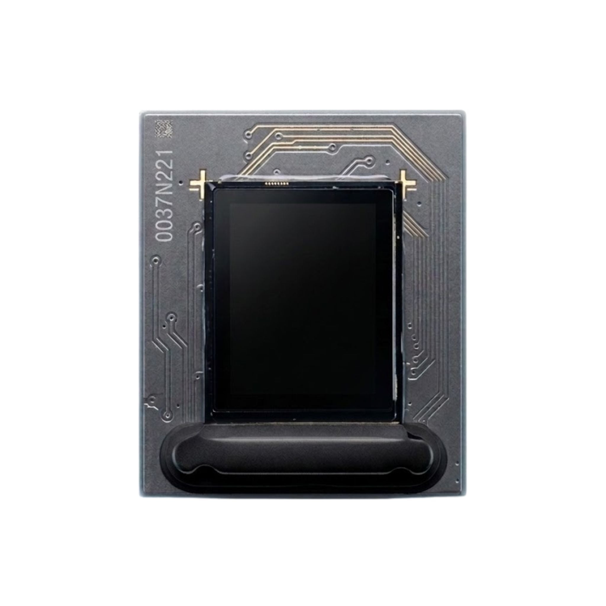
0.39″ Micro-OLED Display — 1024×768 XGA, 1,800 cd/m² Max Luminance
This 0.39-inch silicon-based Micro-OLED display is specified for compact near-eye and embedded optical systems that need XGA resolution, small size, low power operation, and multiple control interface options.
The module uses a 0.18 μm CMOS silicon backplane and top-emission Micro-OLED architecture. Public product information lists 1024(H) × 768(V) pixels, 7.8 μm × 7.8 μm pixel pitch, typical luminance of 600 cd/m², and maximum luminance of 1,800 cd/m².

Technical Specifications
The following values are based on the current product information available for DMGXO0039XGNA. Final electrical, optical, mechanical, and reliability limits should be confirmed with the latest supplier datasheet before PCB layout, optical engine tooling, or volume procurement.
| Parameter | Specification | Engineering Note |
|---|---|---|
| Display Type | Silicon-based active matrix Micro-OLED, top-emission | Use as a component display module; finished-device suitability depends on host electronics, optics, thermal design, and validation. |
| Resolution | 1024(H) × 768(V) pixels, XGA | Suitable for compact viewfinder, near-eye, or embedded visualization projects where XGA detail is acceptable. |
| Diagonal Size | 0.39 inch / 9.9 mm | Small format for compact optical module design. |
| Active Area | 8.1325 mm × 6.1779 mm | Use this value when calculating magnification, field of view, and optical path layout. |
| Pixel Pitch | 7.8 μm × 7.8 μm | Pixel visibility depends on magnification, optics, viewing distance, and system image processing. |
| Pixel Arrangement | RGB vertical stripe | Confirm sub-pixel orientation against optical rotation and mirroring requirements. |
| Luminance | 600 cd/m² typical / 1,800 cd/m² maximum | System eye-box brightness depends on lens, combiner, waveguide, or prism loss; verify on the complete optical engine. |
| Contrast Ratio | >10,000:1 | Panel-level contrast can be affected by optical coatings, stray light, and ambient-light conditions. |
| Uniformity | ≥90% | Validate uniformity after assembly and optical alignment. |
| Frame Rate | 25 Hz – 75 Hz | Select the refresh mode according to power, video timing, image content, and user comfort requirements. |
| Video Input Format | 24-bit RGB 4:4:4; 24-bit YCbCr 4:4:4; 16-bit YCbCr 4:2:2; 8-bit mono | Confirm source format and timing compatibility during controller selection. |
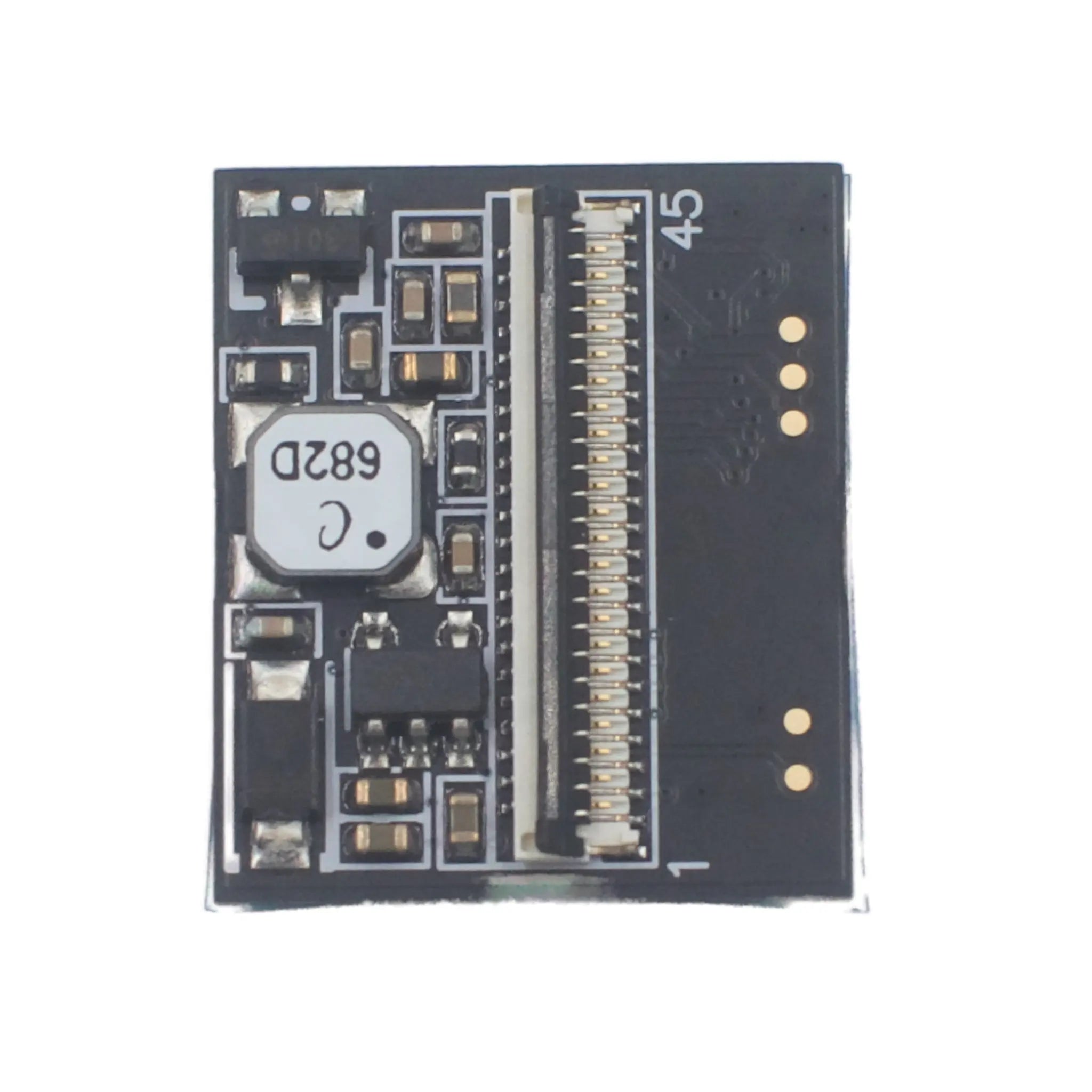
| Control Interface | 3-wire SPI, 4-wire SPI, MCU, I²C 10 kHz – 400 kHz | Register control, initialization, brightness, and image settings should follow the latest datasheet. |
| Supply Voltage | 1.8 V digital; 5.0 V analog | Power rail tolerance, sequencing, ripple, and shutdown behavior should be verified before board release. |
| Power Consumption | 54 mW at 25 Hz; 65 mW at 60 Hz | Power varies with brightness level, frame rate, image content, and driving settings. |
| Color Coordinates | CIE-x: 0.31 ± 0.05; CIE-y: 0.33 ± 0.05 | Use final device calibration when color accuracy is important. |
| Operating Temperature | −40°C to +65°C | Thermal performance should be validated under maximum brightness and continuous operation. |
| Storage Temperature | −40°C to +80°C | Storage limits are non-operating conditions; confirm packaging and logistics requirements. |
| Weight | 1 g | Useful for wearable and compact handheld optical assemblies. |
| Process Node | 0.18 μm CMOS | Listed as silicon CMOS process information; avoid presenting it as independent manufacturing certification. |
Engineering Notes for Integration
Host and timing compatibility
Confirm whether the target controller will use RGB, YCbCr, mono input, SPI, I²C, or MCU control. Register settings, initialization timing, and gamma configuration should follow the latest supplier documentation.
Low-power operation, with conditions
The listed 54 mW and 65 mW values are tied to specific refresh-rate conditions. Actual system power will change with brightness, frame rate, image pattern, optical efficiency, and driver configuration.
Brightness after optical loss
Do not use panel luminance alone as the final user-visible brightness. Calculate and test the complete optical path, including lens, prism, coating, combiner, or waveguide loss.
Validate under real operating load
Check temperature rise under high brightness, continuous operation, and enclosure constraints. Keep use within the listed operating temperature range and define derating rules for the final product.
Application Fit by Engineering Requirement
AR / compact viewfinder evaluation
The 0.39-inch format, 7.8 μm pixel pitch, and 1,800 cd/m² maximum panel luminance may support compact optical-engine evaluation. Final AR suitability depends on waveguide efficiency, field-of-view target, eye-box design, thermal limits, and optical certification requirements.
Industrial and inspection devices
The small active area, low listed power consumption, and wide operating-temperature range can be useful for portable measurement instruments, inspection devices, and embedded visualization systems after host-side validation.
Visualization component evaluation
The display may be evaluated for medical visualization hardware, but it is a display component only. Clinical performance, patient-contact safety, sterilization compatibility, and regulatory approval must be handled at the finished-device level.
Sample and supply confirmation
Before prototype build, confirm sample availability, current lead time, lifecycle status, datasheet version, register documentation, acceptance criteria, and long-term supply plan with DisplayModule.
Request Datasheet, Samples, or Integration Review
Share your target optical architecture, input format, control interface, brightness target, operating environment, expected annual quantity, and prototype schedule. DisplayModule can help confirm whether this 0.39-inch Micro-OLED fits your engineering requirements.