



Can USB-C Drive a Micro OLED?
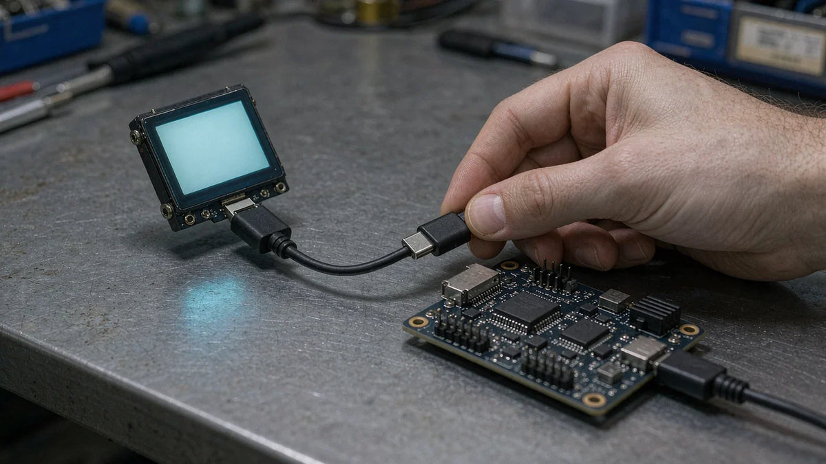
Yes—with a compatible active driver board, not a passive cable. For a MIPI-input Micro OLED, the route covered here is a USB-C source with DisplayPort Alt Mode, an active DisplayPort-to-MIPI DSI bridge, and firmware configured for the exact panel. The board must also provide, or work with, the panel's required power supplies and startup sequence. USB-C, also called Type-C, defines a connector and cable system; the connector alone does not guarantee video output .
A Type-C to MIPI Micro OLED setup therefore needs two separate checks: can the source deliver video to the board, and can the board drive this particular panel? A USB-C connector on a board might be a video input, a power input, or a USB data connection. Check its documented function before buying or connecting it.
What a Working USB-C to MIPI Connection Needs
USB-C DisplayPort Alt Mode source → active video bridge → panel-specific MIPI DSI output → Micro OLED. Firmware and power sequencing are part of the board-to-panel connection, not optional accessories.
| Part of the chain | What to verify |
|---|---|
| USB-C source | The specific port supports DisplayPort Alt Mode and the intended resolution and refresh rate. |
| Active bridge board | Its input accepts USB-C DisplayPort Alt Mode. Its output supports the panel's MIPI interface and timing. An HDMI-only input is not a direct USB-C video input. |
| Panel configuration | The firmware supports the exact panel part number, including initialization commands, lane configuration, reset timing, and display mode. |
| Power and physical connection | Supply rails, sequencing, connector pinout, flex orientation, and input power requirements match the board and panel documentation. |
The active-conversion distinction also applies to HDMI-to-MIPI adapters, but that does not make an HDMI bridge a USB-C bridge. Confirm the actual input interface and any additional conversion stage.
Check direction explicitly: the setup here receives video from a USB-C source and sends MIPI DSI to a panel. A bridge designed for the opposite direction is not interchangeable.
Does Your USB-C Port Output Video?
For this connection, look for explicit DisplayPort Alt Mode support in the source documentation. VESA describes Alt Mode as reusing some or all of the four USB-C high-speed lanes for DisplayPort, with auxiliary communication and hot-plug signaling handled through the Type-C connection .
Do not use a historical lane rate as a compatibility guarantee. VESA's 2014 announcement discusses 5.4 Gbps and 8.1 Gbps per-lane DisplayPort rates; these are specifications discussed in that announcement, not a universal limit or a promise for every USB-C port . The usable input mode depends on the actual source, cable, and bridge. A DisplayPort bandwidth figure alone does not establish what a MIPI panel can display.
The DisplayPort interface overview explains the different carriers. For a purchase decision, ask for the supported modes of the specific USB-C port and board rather than relying on the connector shape or the word “DisplayPort.”
Will the Bridge Drive Your Exact Micro OLED?
This guide covers Micro OLED panels with a MIPI DSI input; it does not assume that every Micro OLED uses the same interface. MIPI DSI-2 is a display-interface specification, not a panel-compatibility certification . The panel datasheet must identify the interface and physical layer that the bridge needs to support.
For D-PHY-based panels, check the clock and data-lane arrangement, lane rate, and timing in the datasheet. Do not apply that wiring model to every DSI-2 implementation. MIPI's DSI overview identifies D-PHY as the physical layer for DSI and describes the interface's low-power display applications . The MIPI DSI interface overview and DSI introduction provide background; the panel documentation controls the actual configuration.
| Compatibility item | Evidence to request |
|---|---|
| Exact panel support | Supported panel part number and revision, with the matching board firmware version. |
| MIPI configuration | Physical layer, lane count, lane rate, pixel format, and command or video mode. |
| Video timing | Active resolution, refresh rate, blanking, and clock requirements supported at the panel output. |
| Startup and control | Required reset sequence and initialization commands, plus documented brightness or gamma control where applicable. |
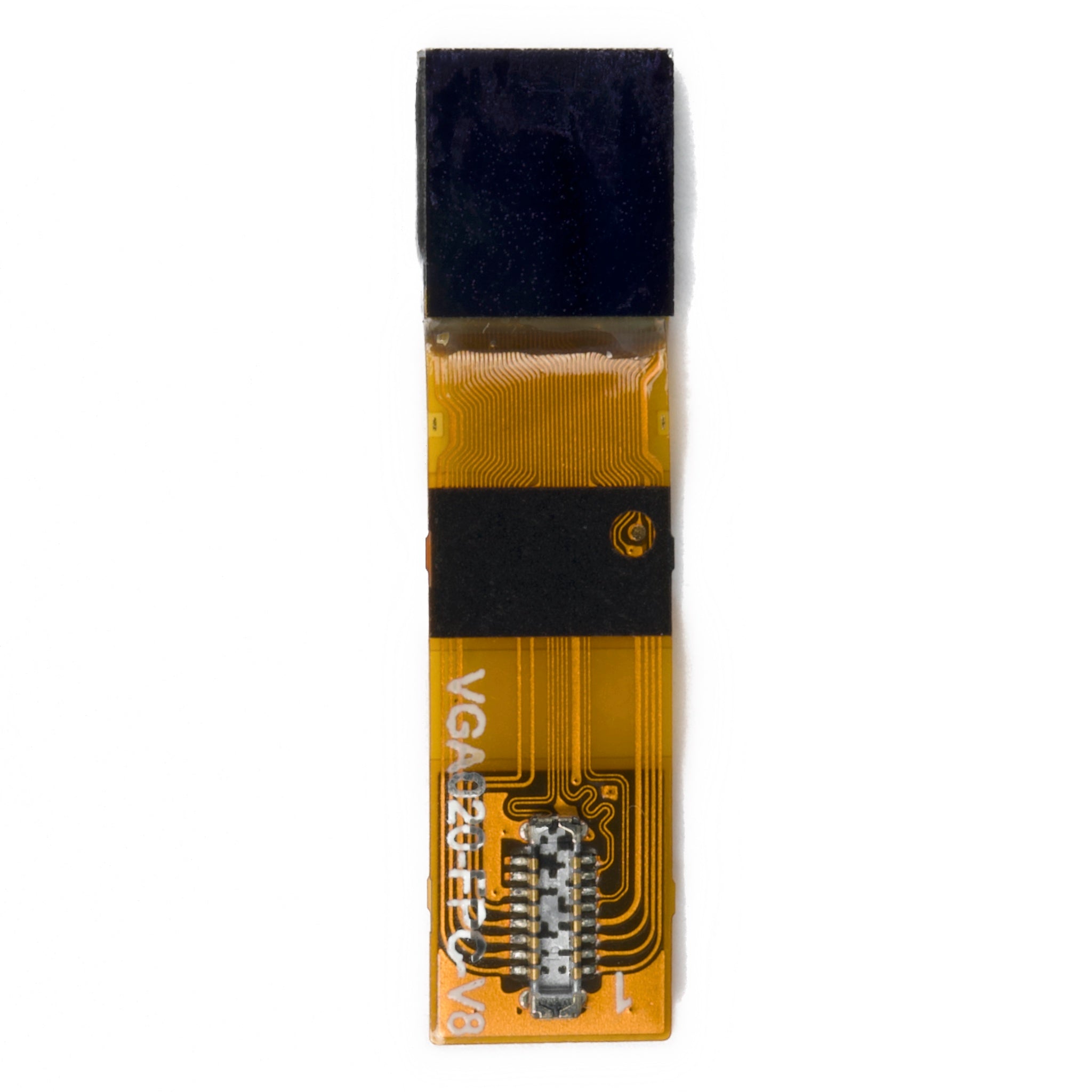
| Electrical and mechanical fit | Power-rail values and sequence, connector pinout, flex pitch, contact orientation, and mechanical clearance. |
Two 1920 × 1080 panels are not automatically interchangeable. As the guide to swapping DSI panels explains, pinout, power, timing, and initialization software must also match. The Micro OLED driving guide covers the associated lane, timing, and command requirements.
Why a Passive Cable Is Not Enough
DisplayPort Alt Mode and MIPI DSI are different interfaces. Rewiring contacts does not decode DisplayPort video, generate a compatible MIPI output, or send the panel's initialization commands. The same distinction between wiring and conversion appears in the explanation of why a passive display cable is not a signal converter.
Power is a separate requirement. USB Power Delivery supports negotiated power arrangements, but it does not replace the panel's regulated supplies and required sequencing . Confirm whether the bridge generates the panel rails, requires external supplies, or needs a separate power input. One cable for video and board power is possible only when the complete power arrangement supports it.
A Documented First-Power-On Checklist
Before testing, create a compatibility record using the source manual, board manual, panel datasheet, and firmware release information. Treat the following as a verification procedure, not a report of a tested board-and-panel combination.
- Identify the hardware. Record the source model and USB-C port, cable specification, bridge revision, panel part number, and firmware version.
- Match both video ends. Choose a documented source input mode and confirm the resulting panel output timing. Do not assume the bridge scales or converts frame rates unless its manual says so.
- Check power before connection. Compare supply requirements and connector pinouts with both manuals. Power down before attaching or reseating a panel flex.
- Use the prescribed startup sequence. Follow the board and panel instructions rather than inventing rail voltages, reset delays, or register values.
- Record the result. Note the selected input mode, displayed image or symptom, and any changes. If changing a setting is permitted, change one documented variable at a time.
A useful supplier confirmation names the exact source mode, board revision, firmware version, and panel part number. “Supports MIPI” alone is not evidence that your combination has been tested. Ask for a demonstration or test record tied to those identifiers if you need proof before purchase.
What to Check When There Is No Image
A blank panel does not identify a single fault. Use these checks to narrow the problem without treating a symptom as proof of its cause.
| Symptom | Possible causes | Next check |
|---|---|---|
| No video through the USB-C connection | Missing Alt Mode support, unsuitable cable, unsupported mode, or link configuration problem. | Check the source manual. Test the same port with a known-working DisplayPort Alt Mode display and suitable cable. A failed test still needs diagnosis; it does not prove the port lacks video capability. |
| Board has power but panel remains blank | Missing input video, incompatible firmware, incorrect reset sequence, or panel power problem. | Check the board's documented input-status indication, then compare firmware and panel identifiers. A power LED alone does not prove a valid video link. |
| Unstable or distorted image | Unsupported timing, link integrity, power, or connection issue. | Select a mode documented for both ends. Inspect the flex with power off; follow the manual for any electrical measurements. |
| Flicker or shutdown | Power instability or another board/panel fault. | Verify the supply against the specified input requirements. Have qualified personnel check panel rails where the documentation permits; do not assume brightness alone identifies the cause. |
When USB-C Is the Right Route
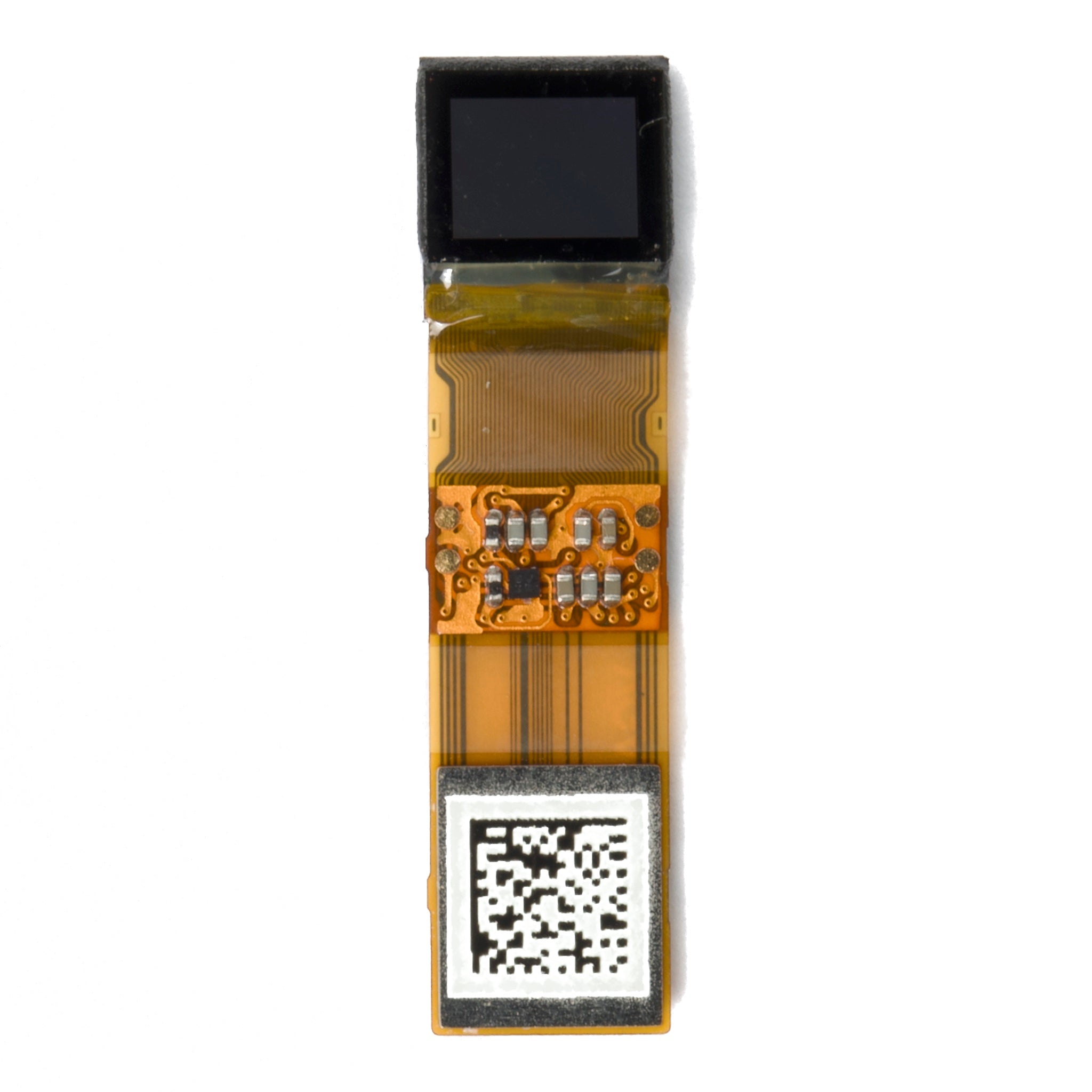
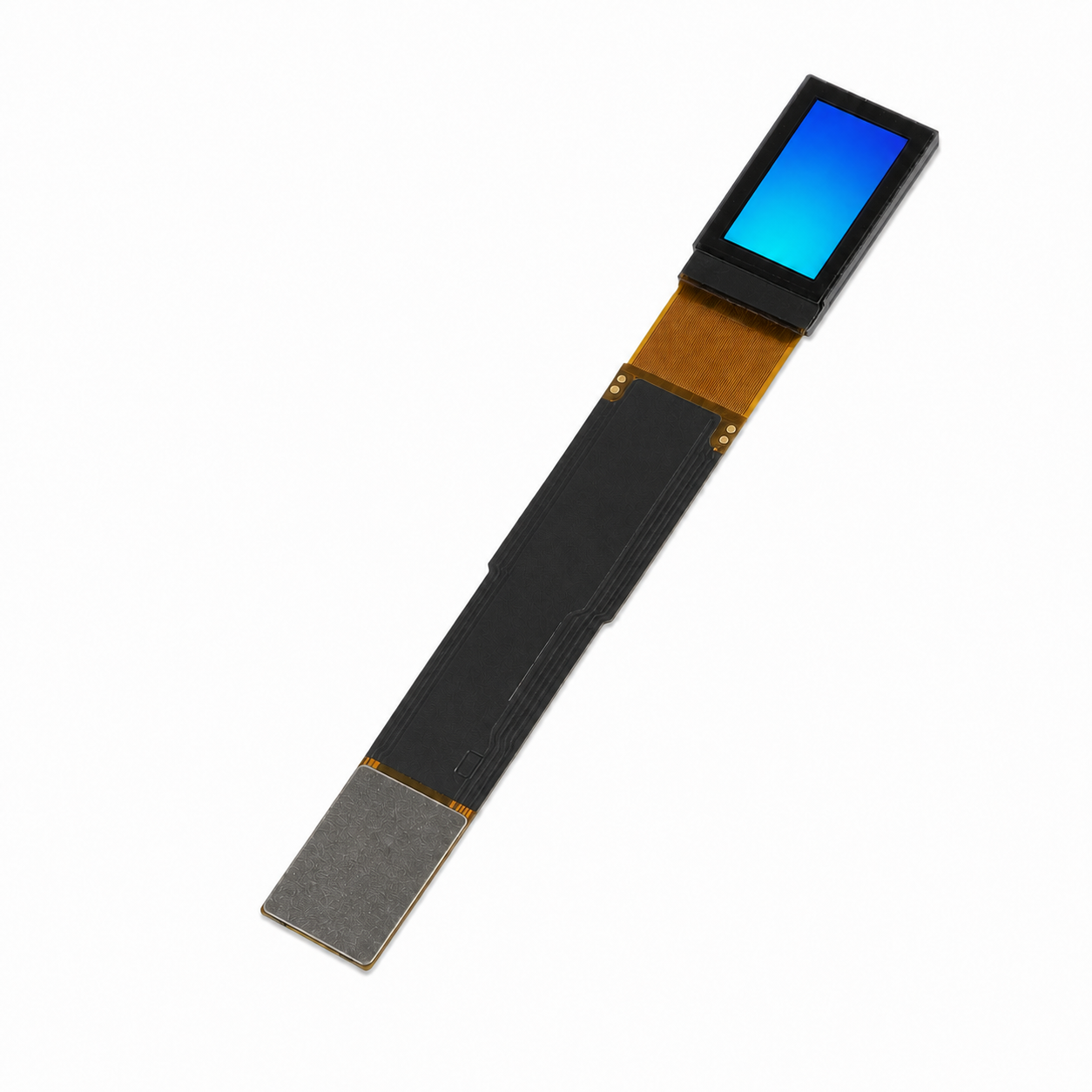
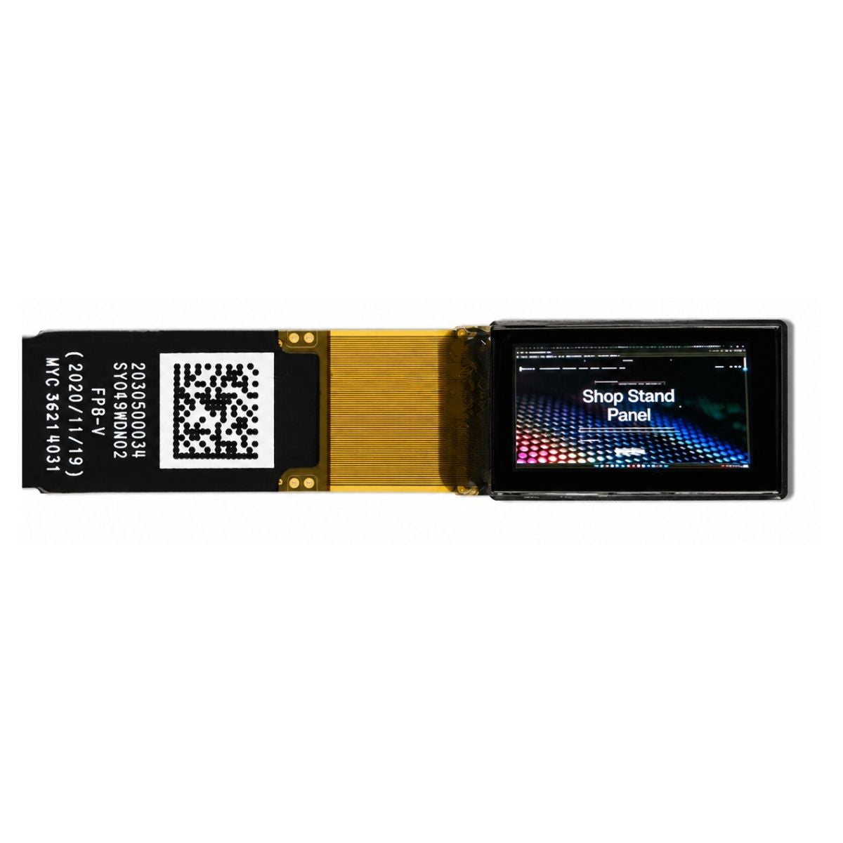
A USB-C bridge is useful when a PC or embedded host needs to feed a bare MIPI panel for evaluation. Near-eye prototypes and viewfinder work are relevant applications; a Micro OLED monitor also involves optics and a complete display system, not just a panel connector.
If the host already has a compatible native MIPI output, compare that route before adding a USB-C receiver and bridge. Native MIPI still requires matching panel firmware, timing, and power. Beyond the interface, Micro OLED selection parameters such as brightness, resolution, power, and lifetime remain part of the design decision.
Frequently Asked Questions
Can a laptop drive a Micro OLED over USB-C?
Yes, if its USB-C port provides the required video output and the connected active driver supports the exact panel. A laptop connected to a complete USB-C display may use electronics already inside the display; that is different from connecting directly to a bare panel.
Is a product labeled USB-C to MIPI enough?
No. Confirm the input protocol, conversion direction, supported panel list, firmware version, and power requirements. A USB-C connector or a matching output socket is not a compatibility guarantee.
Does every Micro OLED need the same driver board?
No. A bare panel needs compatible drive electronics, while a complete module may already include them. Even boards supporting several panels can require different firmware or configuration for each one.
Bottom Line
USB-C can be the video connection for a Micro OLED system, but it is not a direct replacement for MIPI DSI. For the Alt Mode route, verify the source, active bridge, panel configuration, and power plan together. Buy against an exact compatibility record, not a connector label.
Planning a Type-C to MIPI build? Share your source model, panel part number, target resolution, and refresh rate to discuss board and firmware compatibility.
Get a QuoteReferences
USB Implementers Forum. USB Type-C Cable and Connector Specification document page.
VESA. VESA Brings DisplayPort to New USB Type-C Connector. September 22, 2014.
MIPI Alliance. MIPI DSI-2 specification overview.
MIPI Alliance. MIPI Display Serial Interface overview.
USB Implementers Forum. USB Charger and USB Power Delivery overview.
Read more
Your AR image can look misaligned because the display is not aligned with your pupils, the two eye views use the wrong calibration, or the software places virtual content incorrectly relative to th...
Choose the mode supported by both your panel and host first. If both support Command Mode and the panel can retain the image, infrequent or partial updates can reduce link activity. Choose Video M...
Leave a comment
This site is protected by hCaptcha and the hCaptcha Privacy Policy and Terms of Service apply.