


Overview of MIPI DSI Interface
Introduction
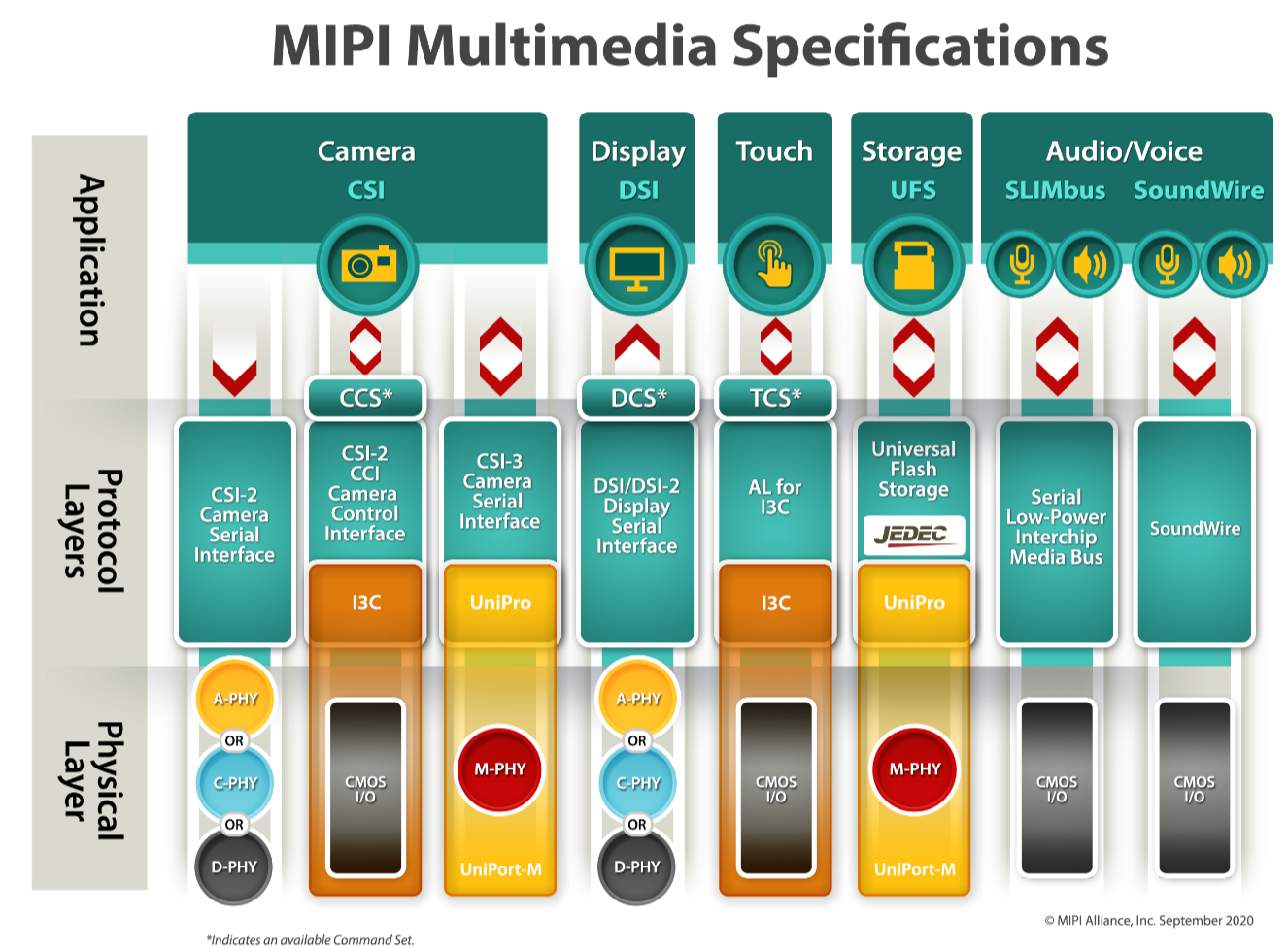
MIPI : Mobile Industry Processor Interface.MIPI Alliance was founded in 2003 by ARM, Nokia, ST,TI etc., including Phone manufacturers, semiconductor manufacturers, software manufacturers, system suppliers, peripheral equipment manufacturers, intellectual property providers. The goal of the alliance is to standardize internal interfaces such as cameras, display interfaces, and RF/baseband interfaces in order to reduce complexity and increase design flexibility. MIPI is not a single interface or protocol, but contains a set of protocols or standards to meet the unique requirements of different subsystems within the phone, such as camera interface CSI, display interface DSI, radio frequency interface DigRF, microphone/speaker interface SLIMbus, etc. The advantage of a unified interface standard is that mobile phone manufacturers can flexibly select different chips and modules from the market according to their needs, making it faster and easier to change the design and function.

Term Explanation
- DCS(Display Command Set):A standardized set of commands for the command mode display module
- CSI(Camera Serial Interface):Defines a high-speed serial interface between the processor and the camera module.
- DSI(Display Serial Interface):Defines a high-speed serial interface between the processor and the display module.
- D-PHY : Provides physical layer definitions for DSI and CSI
DSI Instruction

D-PHY
Describes a synchronous, high speed, low power, low cost PHY(PHY defines the transmission medium, input/output circuit, clock, and signal mechanism).
Configuration
- One Clock lane
- One or multi data lanes

Transmission Mode
- Low-Power Mode(for control):10MHz (max)
- High-Speed Mode(for high-speed data transmission):80Mbps ~ 1Gbps/Lane
Lane Management Layer
According to N(N is 4 at most) data channels set in the design, the layer divides the data to be sent into N groups according to the channel order and sends it to the corresponding data channel, so that it can be sent to the slave at the same time through the data channel. At the receiver , what this layer needs to do is to combine the N groups of data received together to restore the original data sequence.

Lane Type:
Single Clock Lane
- Master:HS-TX, LP-TX
- Slave:HS-RX, LP-RX
Unidirectional data Lane
- Master:HS-TX, LP-TX
- Slave:HS-RX, LP-RX
Bidirectional data Lane
- Master, Slave:HS-TX, LP-TX, HS-RX, LP-RX, LP-CD
Data Lane Operating mode
- Escape mode
- High-Speed(Burst) mode
- Control mode
Low Level Protocol Layer
Information is transmitted in packet format, including long packets and short packets. When sending data, the data is compressed according to the information type and content to complete the generation of ECC codes and the addition of CRC codes. When receiving data, error detection and error correction are carried out on the whole packet according to ECC code and CRC code, and the decoding of packet header and data content is completed and reasonably transmitted to the application layer.
Application Layer
According to the requirements of the application module. At the sender , the sent commands and data are preliminarily encoded into the format specified by MIPI-DSI. While at the receiver , the received data is restored to the data format supported by the application module and the sequence requirements.
Read more

The Birdbath optical solution is widely used in AR glasses due to its low cost and high-quality imaging. In this article, we explore the structure of the BB optical scheme to understand why it is ...

Virtual Reality (VR) technology is becoming increasingly popular, promising immersive experiences for users. However, many VR devices are affected by a visual phenomenon known as the "screen door e...
Leave a comment
This site is protected by hCaptcha and the hCaptcha Privacy Policy and Terms of Service apply.