



Can You Add Touch to AMOLED?
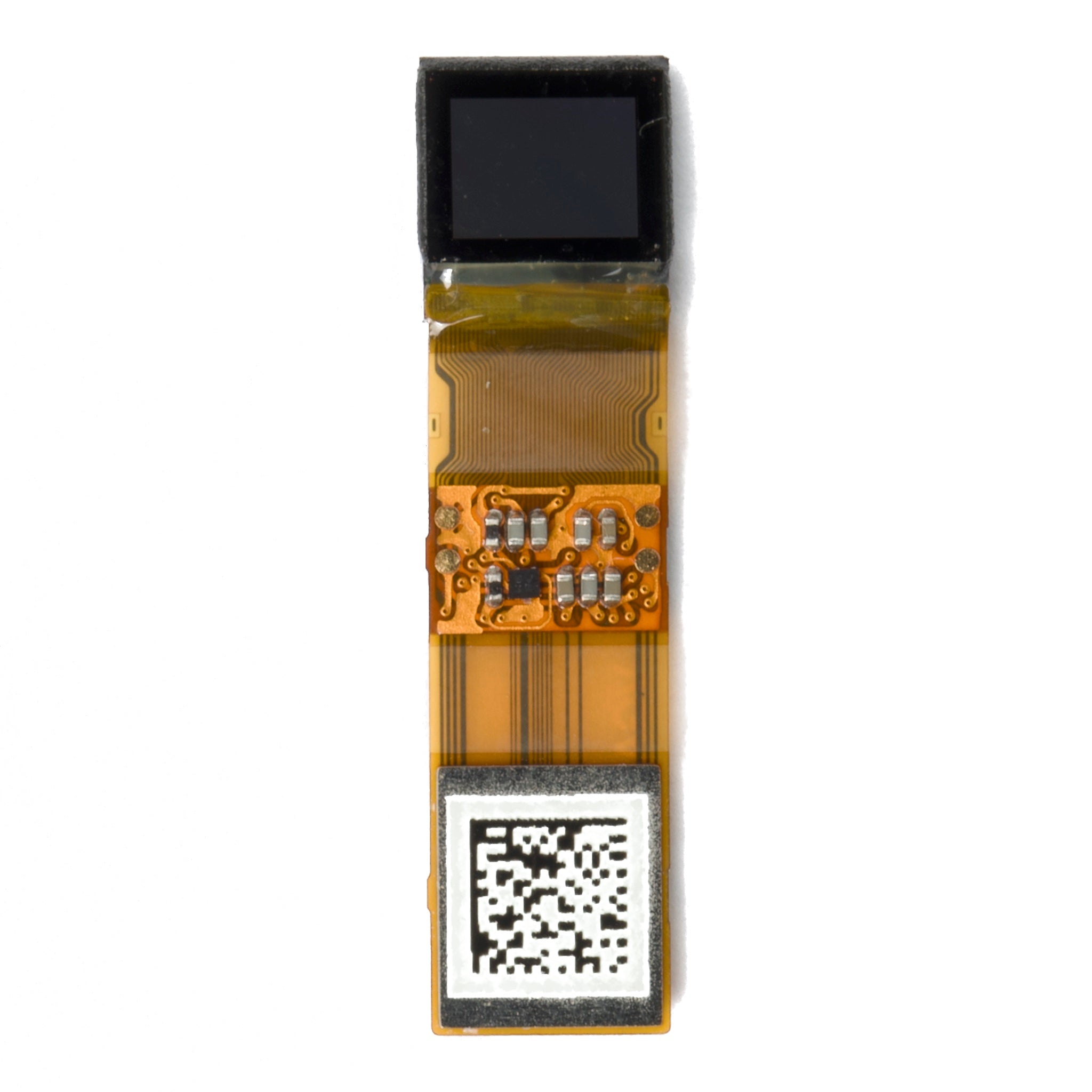
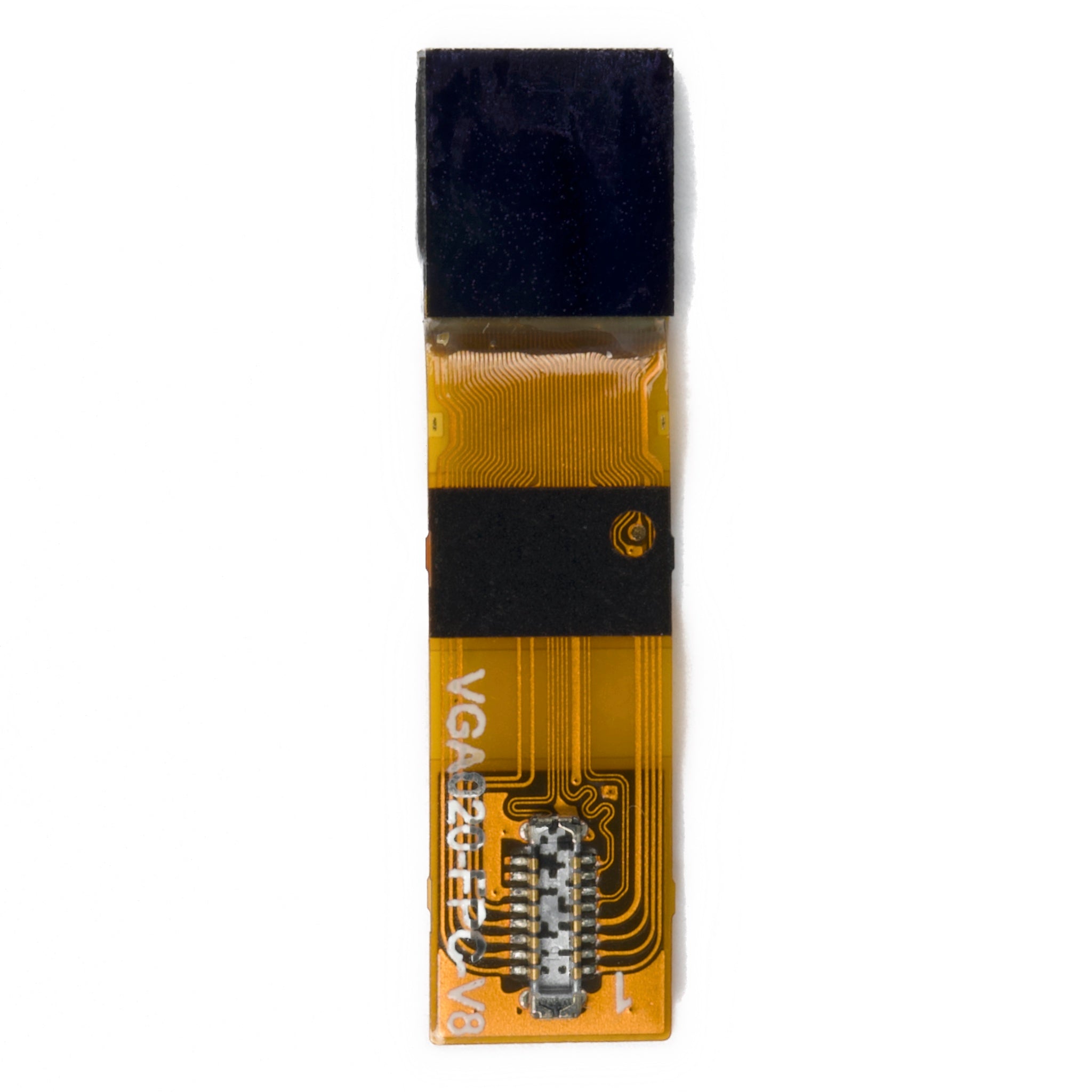
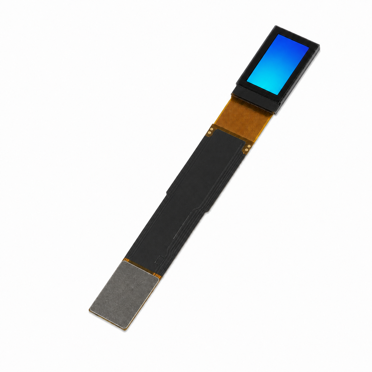
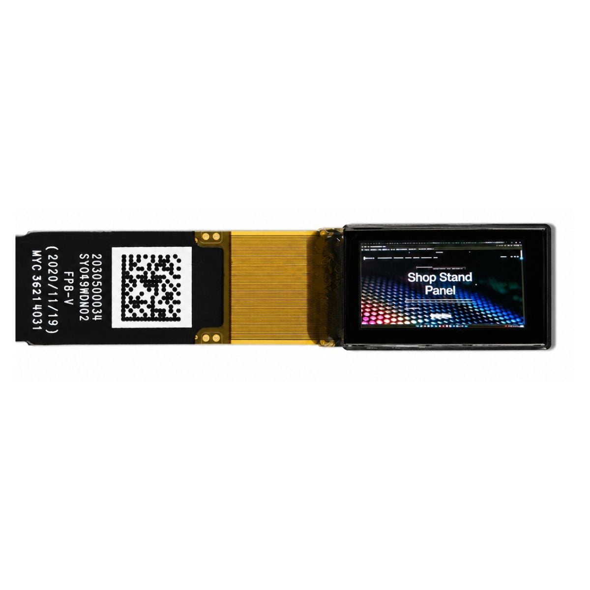
Yes. You can add touch to an AMOLED display by integrating a compatible touch sensor and controller. For an embedded product, a bonded AMOLED touchscreen module is an option to evaluate before commissioning a separate touch overlay.
Start with the display size, host interfaces, and intended operating conditions. Ask the supplier to confirm the sensor structure, controller, firmware, cover glass, and testing included in the assembly. DisplayModule's custom display integration service is a starting point for discussing that stack; compatibility still needs to be confirmed for the selected module.
What Adding Touch Means
AMOLED describes the display technology, not a guarantee of touch capability. AMOLED stands for active-matrix organic light-emitting diode: the pixels emit light, while a thin-film-transistor backplane controls them. A product sold as an AMOLED module may include touch, but the specification must say so. The AMOLED and OLED technology comparison explains the active-matrix distinction.
For a capacitive implementation, a transparent electrode pattern senses the finger, and a controller converts the signal into touch data. On a module using MIPI DSI, DSI carries display traffic [1], while DCS defines standardized display commands [2]. Touch data uses the controller's specified host interface. A working image does not, by itself, confirm that touch is connected or supported.
How Touch Sensing Works
For projected-capacitive touch, distinguish self-capacitance [3] from mutual capacitance [4]. These sensing methods help explain how the controller detects contact, but they do not establish a module's finger count or glove performance.
Self-capacitance measures an electrode relative to a reference. In the model described by MIT's design guide, a finger adds a capacitive path through the body toward earth, increasing the measured capacitance [3].
Mutual capacitance measures coupling between transmitting and receiving electrodes. A finger changes the local field and reduces the measured coupling at the affected intersection. Resolving individual intersections supports multi-touch; the controller and firmware determine the supported number of contacts [4].
| Sensing style | Electrodes | Touch effect | Typical use |
|---|---|---|---|
| Self-capacitance [3] | Single electrode against circuit ground | Adds a parallel path to earth, apparent capacitance rises | Single-touch buttons, sliders, wake-on-touch areas |
| Mutual capacitance [4] | Transmitting row plus sensing column, measured at every intersection | Disturbs the local field, coupling between electrodes falls | Multi-touch screens, pinch and zoom gestures |
I2C and USB are established touch-controller host interfaces [4]. MIPI also defines I3C for sensor and control applications [5], but that specification does not establish I3C support on any particular AMOLED touchscreen. Check the actual controller part number and interface before designing the host board.
The capacitive touch background includes a phone-class illustration of up to 5 fingers and around 10 ms response. Those figures are an example in that article, not specifications for your module. Obtain the supported contact count, report rate, and response-time definition separately from the controller or module supplier.
Before sampling, request the supported cover-glass thickness and coating conditions. Agree separately how charger noise, the intended glove material, and moisture will be tested on the assembled product; a controller datasheet alone may not define those system-level results.
Which Touch Structure to Pick
Three structures worth comparing are add-on lamination, one-glass, and on-cell. They are options to ask about, not a promise that every panel supports all three. The overview of touch technology types describes these approaches alongside other integration methods.
With add-on lamination, a separate sensor is bonded into the stack between the display and the cover glass. This permits separate display and sensor selection, but a sensor or controller change still needs compatibility checks and validation. The multi-layer touch-stack discussion gives an example above 1.5 mm with a roughly 5–7% transmittance penalty. Neither figure is a universal AMOLED limit: request the actual stack drawing and a measured optical comparison for the candidates.
With one-glass, the sensor pattern sits directly on the cover glass rather than a separate sensor substrate. This can remove a substrate from the optical path, but thickness and light transmission still depend on the complete stack. The cover glass must meet electrical, mechanical, and coating requirements together.
With on-cell, touch electrodes are integrated onto upper layers of the display structure rather than a separate sensor carrier. This can reduce stack thickness, but the supplier's design determines the final dimensions and tuning requirements. It is not an add-on option that a buyer can assume is available for an existing bare panel.
| Structure | What changes | Trade-off |
|---|---|---|
| Add-on lamination | Separate sensor bonded between AMOLED and cover glass | Separate component selection; additional layers and any component change need validation |
| One-glass | Electrodes patterned directly onto the cover glass | No separate sensor substrate; optical performance depends on the full assembly |
| On-cell | Electrodes integrated onto upper layers of the display structure | Potential thickness reduction; availability and tuning are tied to the panel design |
Tell shortlisted suppliers your diagonal and volume and ask which of the three structures each AMOLED touchscreen supports. Compare only modules where the specification names the structure, the controller part number, and the firmware revision, since equal size and resolution can still hide different stacks.
What to Connect and Test
Treat display bring-up and touch bring-up as separate tasks, even if their signals share one FPC. For a DSI-based module, confirm the display configuration [1] and supported DCS command sequence [2]. Then confirm the touch-controller link, driver, and coordinate mapping. Do not assume that an available display driver also supports the touch controller.
|
Display bring-up
|
Touch bring-up
|
Evaluate display and touch together at the brightness and refresh rate intended for shipment. Where the product uses a charger, compare operation with it connected and disconnected. The round AMOLED touch-panel guide identifies charger-connected testing and glove/moisture validation as integration checks. Use those checks to define the sample acceptance plan, not as evidence that an untested module will pass.
For early display evaluation, an HDMI-to-MIPI bridge is an option only after its output, timing, initialization support, and connector mapping have been checked against the panel. Confirm the touch connection separately; an image through a bridge does not demonstrate touch operation on the final host.
A Sample Validation Record You Can Use
Use the intended production glass for the baseline test and record its thickness and coatings alongside the controller part number and firmware revision. Map reported contacts against visible targets at the center and edges, then repeat with the intended brightness, refresh rate, charger state, glove material, and defined moisture condition. Set acceptable error and missed-contact limits with the supplier before testing.
If a point shifts or a contact is missed, change one condition at a time and log the result. Keep the display pattern and other settings fixed for that comparison. Save the sample identifier, host software version, conditions, and pass/fail results so a later glass or firmware change can be checked against the same baseline.
When to Skip Touch on AMOLED
Adding touch is not always the right answer for an AMOLED build. If a status readout needs only a few commands, compare physical buttons with a touchscreen before committing to the bonded assembly. Buttons avoid a touch-controller driver, but total cost and standby current still need a product-level comparison. The comparison of touch-input technologies provides context for evaluating capacitive and resistive alternatives.
Equipment that must work in rain with thick gloves, or near cutting fluid, calls for a validation plan before signing off capacitive touch on AMOLED. A different input is sometimes the safer choice.
For harsh light, read the AMOLED outdoor comparison on this site alongside the datasheet luminance and reflectance numbers.
Judge sunlight readability on measured luminance and reflectance under the same conditions, using recognized display test methods [6], not on showroom brightness alone.
Ordering Checklist
Once you decide to add touch to AMOLED, agree the following sheet with the supplier before sampling. The round AMOLED supplier guide describes the same practice for bonded modules:
- Display: diagonal or active area, resolution, outline dimensions, module thickness, viewing conditions, operating and storage temperature.
- Touch structure: add-on laminate, one-glass, or on-cell, with the sensor pattern and stack drawing.
- Touch controller: part number, firmware revision, host interface and address, interrupt behavior, maximum cover glass thickness, glove and moisture handling.
- Cover glass: material, thickness, edge profile, anti-fingerprint and anti-reflective coatings with durability data.
- Interfaces: display lane configuration, touch host link, pinout, logic levels, connector positions, FPC length, and bend limits. For I2C, consult the bus specification [7] alongside the controller's register documentation. For USB, identify the implemented device class and report format; the USB-IF library is an official specification entry point, not a module-specific touch protocol [8].
- Quality: pixel-defect rule including edge pixels, cosmetic criteria for the bond line and glass, reliability tests, change notification and end-of-life policy.
Bottom Line
Yes, you can add touch to AMOLED. Choose a compatible sensor and controller, or request a bonded AMOLED touchscreen assembly with the stack and testing clearly specified. Decide from the module drawing, controller documentation, and sample results rather than the word “AMOLED” alone.
Compare optical results under matched conditions using methods appropriate to the display [6]. If a supplier quotes ASTM D1003 haze or luminous transmittance, confirm which transparent-plastic component was tested and how; that standard does not by itself characterize a complete glass-covered AMOLED assembly [9]. Keep the accepted glass, firmware, and test record tied to the module you order.
Need a bonded AMOLED touchscreen for your product?
Share your diagonal, resolution, touch structure, and cover-glass requirements for stack and firmware feedback.
Request a quoteReferences
- MIPI Alliance, Display Serial Interface specification overview: https://www.mipi.org/specifications/dsi — confirms DSI as the display-side specification. Accessed 13 Nov 2026. Applies to display-interface statements.
- MIPI Alliance, Display Command Set specification overview: https://www.mipi.org/specifications/display-command-set — confirms a standardized command set for control and data supply to DSI displays. Accessed 13 Nov 2026. Applies to display-command statements.
- MIT, Capacitive Touch Sensor Design Guide (course lab document): https://circuits.mit.edu/_static/F25/labs/rc/touchsensor_design.pdf — describes self-capacitance measurement as a single electrode against ground, with touch adding a parallel path to earth through the human-body model. Accessed 13 Nov 2026 via indexed content. Applies to self-capacitance statements.
- G. Barrett and R. Omote, Projected-Capacitive Touch Technology (Information Display article, Stanford-hosted course copy): http://large.stanford.edu/courses/2012/ph250/lee2/docs/art6.pdf — describes self- versus mutual-capacitance touch screens, per-intersection measurement enabling multi-touch, and I2C as the standard mobile-controller host interface. Accessed 13 Nov 2026 via indexed content. Applies to mutual-capacitance and host-interface statements.
- MIPI Alliance, I3C sensor specification overview: https://www.mipi.org/specifications/i3c-sensor-specification. Describes the I3C sensor and control interface; does not confirm support on a particular touch controller. Accessed 13 Nov 2026.
- ISO 9241-307:2008, Ergonomics of human-system interaction, Part 307: https://www.iso.org/standard/40102.html — establishes test methods for electronic visual displays. Accessed 13 Nov 2026. Applies to measurement-comparison statements.
- NXP, UM10204 I2C-bus specification and user manual: https://www.nxp.com/docs/en/user-guide/UM10204.pdf — defines the I2C-bus specification used for touch-controller control links. Accessed 13 Nov 2026. Applies to I2C interface statements.
- USB Implementers Forum, Document Library: https://www.usb.org/documents. Official entry point for USB specifications, including device-class documents. The implemented class and report format must be confirmed for the selected controller. Accessed 13 Nov 2026.
- ASTM D1003-21, Standard Test Method for Haze and Luminous Transmittance of Transparent Plastics: https://www.astm.org/d1003-21.html. Applies to transparent-plastic measurements within the method's scope, not automatically to a complete glass-covered display. Accessed 13 Nov 2026.
Read more
Choose the mode supported by both your panel and host first. If both support Command Mode and the panel can retain the image, infrequent or partial updates can reduce link activity. Choose Video M...
Keep moisture out of OLEDs by preserving the factory encapsulation, storing modules in their specified dry packaging, and designing the finished enclosure to control liquid entry and condensation. ...
Leave a comment
This site is protected by hCaptcha and the hCaptcha Privacy Policy and Terms of Service apply.