


The Interface of 8080
Introduction
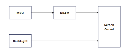
The screen that uses this interface is usually equipped with a driver chip, such as ILI9488, ILI9341, SSD1963, etc. The driver chip has its own video memory, so the MCU just needs to pass the display data to the driver chip, which will save the data to the video memory, and finally display the data in the video memory to the screen.
The 8080 protocol is a kind of parallel, asynchronous, half duplex communication protocol, which can be used for the communication between single chip controller and LCD driver chip.

Interface
Pin definition
- CS : Chip selection signal, active low level
- RES : Reset signal, low active
- D/C : Data command selection end, 0: command; 1: Data
- WR : Write address/data control terminal, active low
- RD : Read data control terminal, active low
- D[17:0] : Data/command signal
- IM2/IM1/IM0 : Interface control. IM2=0 Serial, IM2= 1, IM1=0, IM0=0. 6800/8080 8bit parallel interface; IM1=0, IM0= 1,6800/8080 16bit parallel interface; IM1=1, IM0=0, 6800/8080 9bit parallel interface; IM1=1, IM0= 1,6800/8080 18bit parallel interface
Color data encoding
- 12-bits/pixel (R 4-bit, G 4-bit, B 4-bit), 4,096 Colors,
444; - 16-bits/pixel (R 5-bit, G 6-bit, B 5-bit), 65,536 Colors,
565; - 18-bits/pixel (R 6-bit, G 6-bit, B 6-bit), 262,144 Colors,
666; - 24-bits/pixel (R 8-bit, G 8-bit, B 8-bit), 16,777,216 Colors,
888;
Write Cycle
The WRX signal is driven from high to low and then be pulled back to high during the write cycle. The host processor provides information during the write cycle when the display module captures the information from host processor on the rising edge of WRX. When the D/CX signal is driven to low level, then input data on the interface is interpreted as command information. The D/CX signal also can be pulled high level when the data on the interface is RAM data or command’s parameter.


Read Cycle
The RDX signal is driven from high to low and then allowed to be pulled back to high during the read cycle. The display module provides information to the host processor during the read cycle while the host processor reads the display module information on the rising edge of RDX signal. When the D/CX signal is driven to low level, then input data on the interface is interpreted as command. The D/CX signal also can be pulled high level when the data on the interface is RAM data or command parameter.


Note: Read data is only valid when the D/CX input is pulled high. If D/CX is driven low during read then the display information outputs will be High-Z
Advantage
- Simple and convenient control
- No clock and synchronization signals
- No MCU to provide video memory, no SDRAM or SRAM
Disadvantage
- Cost GRAM
- The driver chip requirements, so it is difficult to do large screen (QVGA above)
- Because with the driver chip, will be more expensive than RGB interface screen
Read more

Imagine driving down a highway, and instead of looking at a screen for navigation, the directions appear right on your windshield. Or, while shopping, you see product information floating in front...

Field of View (FOV) determines how much virtual content AR glasses display—consumer models hit 30-50°, premium reach 70°+. Wider FOV lets users see navigation cues or alerts without turning, enhanc...
Leave a comment
This site is protected by hCaptcha and the hCaptcha Privacy Policy and Terms of Service apply.