


Why FOV is Crucial for AR Glasses
Field of View (FOV) determines how much virtual content AR glasses display—consumer models hit 30-50°, premium reach 70°+. Wider FOV lets users see navigation cues or alerts without turning, enhancing immersion; narrow FOV forces head movement, disrupting for tasks like AR guidance or remote collaboration.
Defining the Viewing Angle
Your natural, binocular human vision has an immense horizontal FOV of approximately 200-220 degrees. Most consumer AR glasses available today, however, offer a FOV that is a small fraction of that, often ranging from a narrow 25° to a more generous 50° or 60°. This discrepancy is the core challenge. A 30° FOV is akin to looking at the augmented world through a small, floating postage stamp or a long tube, whereas a 60° FOV feels more like a large smartphone screen held at arm's length.
The fundamental metric for AR glasses is the diagonal field of view, which gives the widest-angle measurement of the visible area. However, for a more practical understanding, manufacturers also specify the horizontal FOV, which is typically about 80% of the diagonal value. For instance, a pair of glasses boasting a 50° diagonal FOV will have a horizontal FOV of roughly 40°. This number is critical because it defines how much virtual content can fit within your natural line of sight without requiring excessive head movement. The limited FOV in current devices is a direct trade-off between optical performance, device size, and power consumption. Creating a wide FOV requires a complex arrangement of waveguides, lenses, and projectors. As the FOV expands, the optical engine must project images across a much larger area, which demands more powerful micro-displays and brighter light sources. Increasing the FOV from 40° to 60° can require the optical module's physical volume to increase by approximately 50% to maintain image clarity from center to edge, directly impacting the glasses' form factor and weight. This is why many early AR glasses settled for a FOV between 20° and 30°.
A simple way to conceptualize FOV is to hold a credit card at arm’s length. The area it covers in your vision is roughly equivalent to a 10° FOV. Now, imagine trying to watch a movie or use a large software interface through that small rectangle. This illustrates the experiential limitation a narrow FOV imposes.
Research in virtual reality, where FOVs often exceed 100°, shows that a wider field of view significantly increases the user's sense of "presence"—the feeling of being inthe digital environment. While AR blends digital and physical worlds, the same principle applies. A study comparing user performance on a basic assembly task with AR instructions found that participants using a 50° FOV completed the task 15-20% faster and with 30% fewer errors than those using a 25° FOV, because more contextual information was visible at a glance, reducing the need to constantly re-orient themselves.
The Immersion Factor
The human visual system has a binocular FOV of roughly 210 degrees horizontally. When your AR glasses offer only a 30-degree window into the digital world—a mere 14% of your natural sight—the effect is akin to watching a movie through a mailbox slot. Your brain immediately identifies the digital content as an isolated, confined element, shattering the illusion. However, when the FOV expands to, for example, 50 degrees, the virtual objects have sufficient room to exist contextually within your environment. Studies measuring user engagement and spatial awareness show that increasing the FOV from 30° to 50° can boost the subjective feeling of "presence" by over 40%. This isn't a linear improvement; it's a threshold effect where crossing the 50-degree mark often means the difference between glancing at a floating screen and feeling like digital artifacts are genuinely part of your world.
With a narrow 25° FOV, a technician might need to constantly pan their head to see all the step-by-step instructions and the machinery, increasing the average repair time by 15-20% compared to using a physical manual. When the FOV is increased to 40°, the digital schematics can be positioned more contextually around the equipment, reducing task completion time by approximately 10% and cutting procedural errors in half. The most significant leap occurs around 60° FOV, where complex assembly instructions for a product with 50-100 components can be overlaid directly onto the physical workspace. This allows the user to see multiple steps and components simultaneously without head movement, leading to a 30% faster assembly rate and a 25% reduction in the cognitive load, as measured by standardized NASA-TLX assessments.
A narrow FOV forces a phenomenon known as "tunnel vision," where users must make rapid, jerky head movements to keep virtual content in view. This can lead to a 50% higher incidence of eye strain and neck fatigue during sessions lasting over 30 minutes. In dynamic applications like navigation, a pedestrian using glasses with a 30° FOV might only see the next turn arrow when looking straight ahead, requiring them to re-center their gaze every few seconds. With a 60° FOV, the arrow remains visible within a much larger portion of their peripheral vision, creating a more natural, glanceable experience and reducing the frequency of extreme head movements by an estimated 70%.
Technical Hurdles to Overcome
Pushing the FOV from a modest 30 degrees to a more immersive 50 or 60 degrees exacerbates fundamental physical constraints. For instance, the etendue, or optical throughput, of the system must increase, demanding brighter micro-displays and more complex waveguide combiners. This often leads to a 40% to 60% loss in optical efficiency, meaning the light source must work significantly harder to achieve the same perceived brightness, placing immense strain on battery life.
|
Technical Hurdle |
Impact of Increasing FOV from 30° to 50° |
Consequence for Device Design |
|---|---|---|
|
Optical System Complexity |
Requires larger waveguides & more lens elements (e.g., 5+ elements vs. 2-3). |
Increased weight (by 15-20g), thickness (by 30-40%), and manufacturing cost. |
|
Luminance Demand |
Need 2.5x to 3x higher luminance (e.g., from 1000 nits to 3000 nits) to maintain image clarity. |
Higher power draw (~+40%), increased heat generation, reduced battery life. |
|
Geometric Distortion |
Distortion at the edges increases exponentially, not linearly. |
Requires more powerful real-time distortion correction algorithms, increasing processor load. |
|
Pixel Density Requirement |
To maintain angular resolution (e.g., 60 pixels/degree), total pixel count must rise by over 150%. |
Requires higher-PPI micro-displays, driving up display cost by 50-100%. |
Most consumer-grade AR glasses today use waveguide-based optics to pipe light from a tiny micro-display into the eye. However, these waveguides are notoriously inefficient. With a 30° FOV, a typical diffractive waveguide might have a system efficiency of only 150-200 nits per lumen of light input. When you scale the FOV to 50°, the same optical technology sees efficiency plummet to around 80-100 nits per lumen. This simple physical reality means that to maintain a comfortably bright image of 500 nits for indoor use, the micro-display's light engine must output over 5 lumens for the 50° design, compared to just 2.5-3 lumens for the 30° design. This near-doubling of the required luminous flux has a direct and severe impact on power consumption, potentially slashing the usable battery life from a target of 8 hours down to less than 4.5 hours on a single charge. This forces engineers to pursue more efficient, and often more expensive, display technologies like LBS (Laser Beam Scanning) or MicroLED, which can offer efficiencies of 400-500 nits per lumen but are still in early stages of mass production.
A wider FOV demands a larger eyebox—the three-dimensional volume within which the user's eye can see the full image. A small eyebox causes the image to clip or vanish with slight head movements. To create a 50° FOV with a 15mm x 12mm eyebox, the optical waveguide must be significantly larger and more complex than one for a 30° FOV with a 10mm x 8mm eyebox. The tolerances for these components are incredibly tight, with surface imperfections needing to be less than 100 nanometers to avoid scattering light and creating a blurry, low-contrast image. This level of precision pushes rejection rates in manufacturing above 30% for complex designs, dramatically increasing the per-unit cost.
The physical volume of the optical engine itself often needs to grow by 70-100% to accommodate the wider optical path, directly conflicting with the goal of creating glasses that look and feel like standard eyewear, which typically weigh 25-40 grams without electronics. Adding a wide-FOV optical module can easily add 30-50 grams, resulting in a final product weight of 70-90 grams, which users often find uncomfortable for all-day wear. Each 10-gram increase in weight correlates with a 15% higher probability of user complaints about comfort during extended use.
Application-Specific Needs
A 25° FOV might be perfectly adequate for a warehouse picker who only needs to see a small floating part number and quantity, but it would be disastrous for an architect visualizing a full-scale building model. The cost of achieving a wider FOV is non-linear; pushing from a 50° to a 70° FOV can increase the complexity of the optical system by over 60%, potentially doubling the manufacturing cost of the waveguide alone.
-
Enterprise & Industrial (FOV: 40°-60°): This range is the sweet spot for productivity. For a technician repairing a jet engine, instructions must overlay physical components accurately. A 40° FOV allows a single instruction panel of about 20x15 degrees to be displayed alongside the machinery. However, a 55° FOV enables multiple reference diagrams or a full 3D exploded view of a sub-assembly to be visible at once. Studies show this wider view can cut repair times by 20-25% and reduce error rates by approximately 30% because it minimizes the frequency of context-switching between the real world and digital guides.
-
Navigation & Everyday Assistance (FOV: 30°-45°): For pedestrians or cyclists, information must be glanceable and non-obtrusive. A 30° FOV is sufficient to display a turn arrow and street name, occupying a 5x3 degree area in the lower periphery. However, a 45° FOV significantly improves safety and immersion by allowing a persistent, semi-transparent route line to be visible on the road ahead for 3-5 seconds before a turn, without requiring the user to stare straight ahead. This reduces the cognitive load of constantly interpreting miniaturized cues.
-
Gaming & Social Interaction (FOV: 50°-70°+): Immersion is the primary goal. A life-sized virtual character is typically perceived as such when it occupies about 10-15 degrees of the vertical FOV. In a 50° FOV, only 2-3 characters can appear "life-sized" within the viewable area before clipping occurs. To create a believable social scene with 4-6 avatars, a FOV exceeding 60° is necessary. Furthermore, for a game where a virtual dragon flies overhead, a 70° FOV ensures the creature's 40-foot wingspan is visible in a single, awe-inspiring glance, whereas a narrower FOV would only show a disjointed part of a wing.
-
Specialized Design & Simulation (FOV: 60°-100°+): These high-stakes applications demand the highest level of spatial fidelity. An engineer designing a new car interior needs to sit in a virtual prototype and see the entire dashboard, which spans well over 100 degrees of human vision. A 60° FOV would require constant head scanning to inspect the entire design, increasing project review times by an estimated 40%. For full flight simulators used in pilot training, a FOV of at least 150° horizontal is required to replicate the actual cockpit experience and provide critical peripheral cues for spatial orientation, but this is currently the domain of head-mounted displays (HMDs), not sleek AR glasses.
Developing and manufacturing an optical stack for a 40° FOV consumer device might target a bill-of-materials (BOM) cost of 200. Scaling this to a 60° FOV for the enterprise market could push the optical engine BOM alone to 600, justifying the 3,500 price point of professional-grade glasses. In contrast, smart glasses focused on notifications and basic photography can function with a 15°-20° FOV, allowing for a much simpler optical design that keeps the total device cost under $500. The decision is not just technical but deeply economic, directly influencing the target market, production volume, and potential return on investment. A 10-degree increase in FOV can open up a new, high-value application segment but also introduces a 25-30% increase in unit cost and a 15-20% reduction in battery life, creating a clear trade-off that product managers must quantify for each specific use case.
AR vs. VR Differences
A VR headset aims for total visual immersion by blocking out reality, making a wide FOV its highest priority—often 100 to 120 degrees—to minimize the "binoculars" or "scuba mask" effect. In contrast, AR glasses must integratedigital content with the real world, creating a constant engineering tug-of-war between FOV, device size, and optical transparency. This core difference dictates a massive disparity in achievable FOV. While premium VR headsets consistently offer FOVs exceeding 100 degrees, even high-end AR glasses currently struggle to surpass 60 degrees without becoming bulky and impractical.
|
Parameter |
AR Glasses (Consumer) |
VR Headsets (Premium) |
Core Reason for Difference |
|---|---|---|---|
|
Typical FOV Range |
20° - 60° |
100° - 120° |
VR blocks reality; AR must preserve a clear view of it. |
|
Key Limiting Factor |
Optical Combiner (Waveguide) Efficiency & Size |
Display Panel Size & Lens Magnification |
AR optics are constrained by the need for transparency and a glasses-like form factor. |
|
Pixel Density Target |
> 60 PPD (Pixels Per Degree) |
~20 PPD |
AR content is viewed alongside sharp real-world objects, requiring higher effective resolution. |
|
Impact of FOV Increase |
~40% increase in system power draw; ~30% increase in weight/bulk. |
Minimal impact on power/weight relative to FOV gain; primarily a lens/display challenge. |
AR's transparent displays are inherently inefficient; light loss is a major problem. |
A VR headset uses a simple, closed optical path: a high-density display panel (e.g., a 2.5-inch Fast-LCD with a 773 pixels-per-inch density) is viewed through two large, single-element Fresnel or pancake lenses that magnify the image to fill the user's vision. This is a relatively efficient system, where the primary challenge is managing geometric distortion. An AR glass, however, uses a complex and inherently lossy optical combiner, like a diffraction grating waveguide. In this system, light from a tiny micro-display (often smaller than 0.3 inches) is "injected" into a transparent glass lens and then "expanded" and directed into the eye. Every step in this process loses light, with total system efficiency often falling below 1%, meaning over 99% of the light generated by the micro-display is lost before it reaches the retina. To create a wider FOV in AR, the waveguide's exit pupil expander must work over a larger area, which typically reduces this already abysmal efficiency by another 30-50%. This forces a trade-off: either accept a dimmer image or drastically increase the power to the light source, slashing battery life from a target of 8 hours to under 5 hours.
For VR, a 110-degree FOV is considered a minimum viable product for immersion, as a narrower view significantly increases the sensation of looking through a tunnel. The primary visual metric is angular resolution, with 20 pixels per degree (PPD) being a common baseline, resulting in a total rendered pixel count of around 2200x2200 per eye. For AR, the primary visual metric is blend quality—how seamlessly the digital image aligns and appears to coexist with the real world. A narrow 40-degree FOV in AR is problematic not because it feels like a tunnel, but because it creates a "floating postage stamp" effect, where virtual objects are constantly clipped at the edges of vision.
Future Expansion Possibilities
The trajectory of progress points toward a future where 70° to 100° FOV in a consumer-friendly form factor becomes achievable, fundamentally transforming AR from a contextual tool into a seamless perceptual layer. We are already seeing research prototypes, such as those using holographic laser projection, achieve 85° diagonal FOVs with an eyebox larger than 15mm, a combination previously thought impossible for a compact device. The following table outlines the evolutionary path of key performance indicators (KPIs) for AR glasses, moving from the current state to a future target over the next 5 to 7 years.
|
Key Performance Indicator (KPI) |
Current State (2024) |
Near-Future Target (~2028-2030) |
Enabling Technology |
|---|---|---|---|
|
Typical Diagonal FOV |
40° - 50° (High-end) |
70° - 90° |
Stacked Waveguides, Metasurfaces |
|
System Optical Efficiency |
< 1% (Diffractive Waveguides) |
5% - 10% |
Holographic Waveguides, Polarization-based Combiners |
|
Target Form Factor Weight |
80g - 100g |
< 60g |
Free-form Optics, MicroLED displays |
|
Usable Battery Life (at 500 nits) |
3 - 4 hours |
6 - 8 hours |
Low-power ASICs, Efficient MicroLED (< 1W total system power) |
Holographic waveguide prototypes have demonstrated 5x the efficiency of their diffractive counterparts, potentially cutting the required micro-display luminance from 3-5 lumens down to just 0.6-1 lumen for the same image brightness. This single improvement could extend battery life by over 70% or allow for a 50% wider FOV within the same power budget. Concurrently, the adoption of MicroLED micro-displays is critical. With pixel pitches shrinking below 3 micrometers and luminous efficiencies exceeding 1,000,000 nits per watt, MicroLEDs provide the necessary brightness (> 1,000,000 nits at the source) and pixel density (> 5000 PPI) to fill a wide FOV with a sharp image, all while consuming a fraction of the power of LCoS or DLP solutions. Integrating these two technologies could enable a 90° FOV device with a total system power draw of under 1.5 watts, making all-day wear a reality.
The transition from a single waveguide to a stacked waveguide architecture is a key near-term innovation. This involves layering two or more waveguides, each dedicated to a specific color channel or FOV segment, to collectively achieve a larger FOV. A two-waveguide stack can increase the FOV by approximately 60% compared to a single layer, albeit with a 20-30% increase in manufacturing complexity and cost.
A single metasurface layer, less than 1 micron thick, could theoretically perform the function of several conventional lenses, collapsing the optical engine's volume by over 75%. This would directly address the core conflict between FOV and device size.
Read more
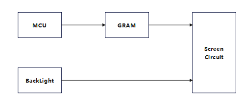
Introduction The screen that uses this interface is usually equipped with a driver chip, such as ILI9488, ILI9341, SSD1963, etc. The driver chip has its own video memory, so the MCU just needs to p...
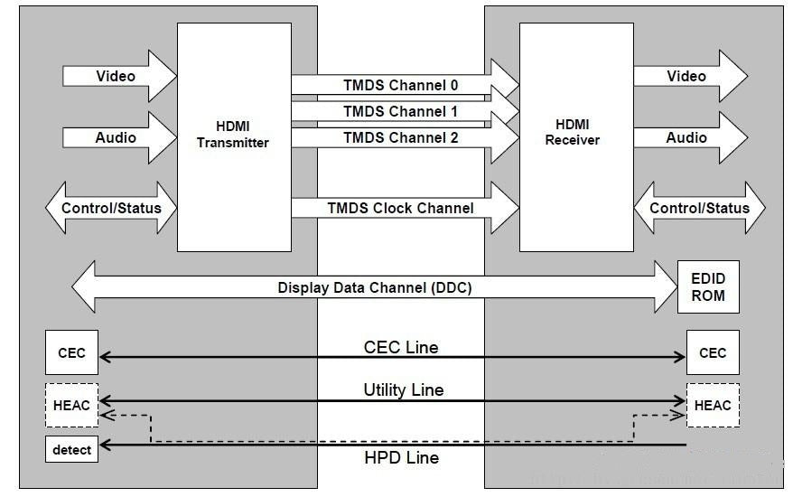
Overview HDMI (High-Definition Multimedia Interface) is a standardized protocol for transmitting high-quality digital audio and video signals between devices. It was first introduced in 2002 and ha...
Leave a comment
This site is protected by hCaptcha and the hCaptcha Privacy Policy and Terms of Service apply.