


AR Optical Waveguide Module 1280x720
- 💹 Enjoy a 20% discount for orders over 500
- 📉 A 15% discount is available for orders ranging from 200 to 499
- 🎁 A 10% discount is available for orders ranging from 50 to 199
- 🎁 A 5% discount is available when ordering 10-49
Order samples, immediate delivery.
Factory bulk lead time: 3 weeks.
Interested in customizing this product? Get in touch with us.
AR Optical Waveguide Module 1280x720
- 💹 Enjoy a 20% discount for orders over 500
- 📉 A 15% discount is available for orders ranging from 200 to 499
- 🎁 A 10% discount is available for orders ranging from 50 to 199
- 🎁 A 5% discount is available when ordering 10-49
Resources & Downloads
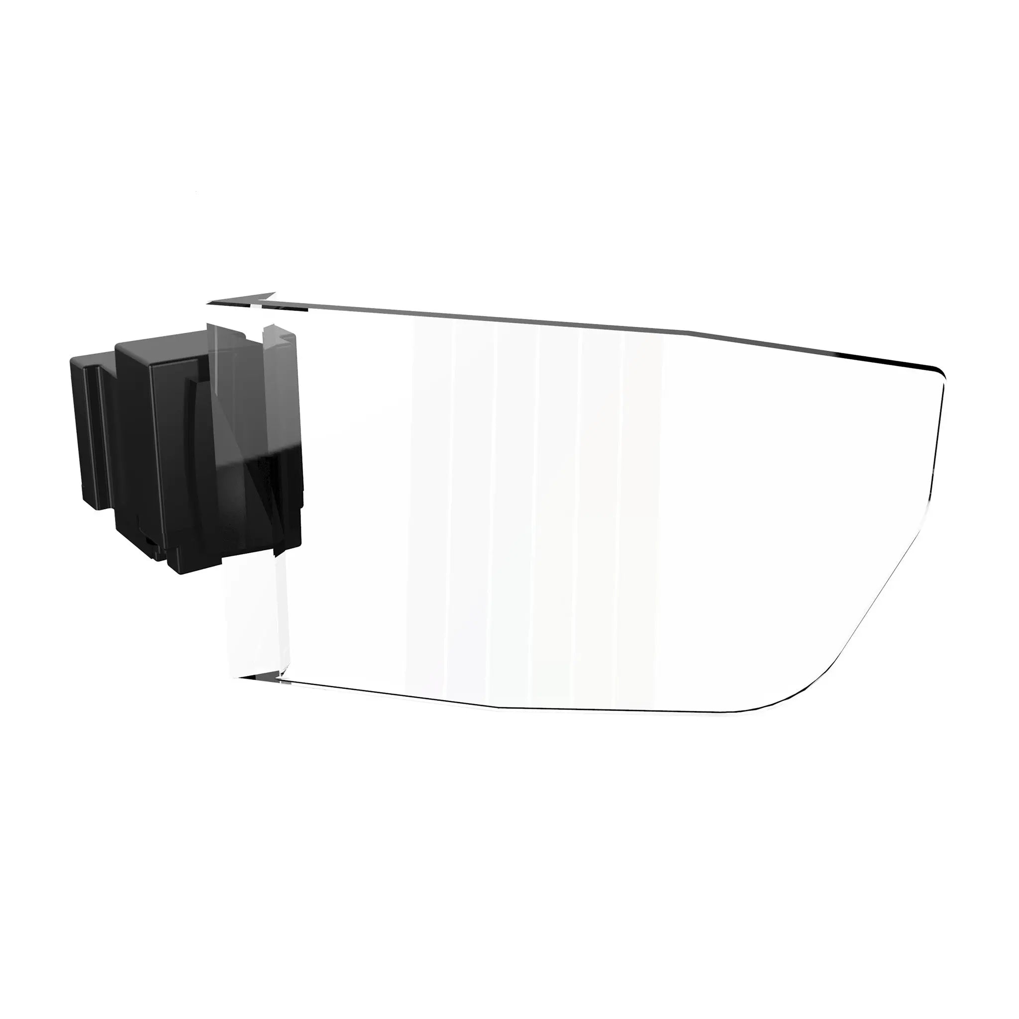
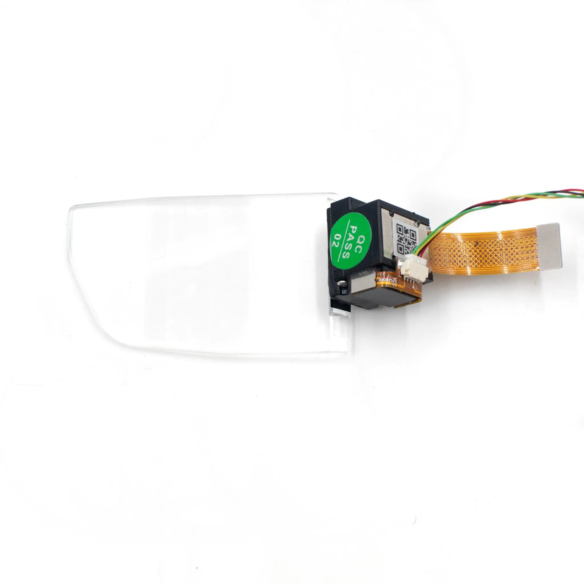
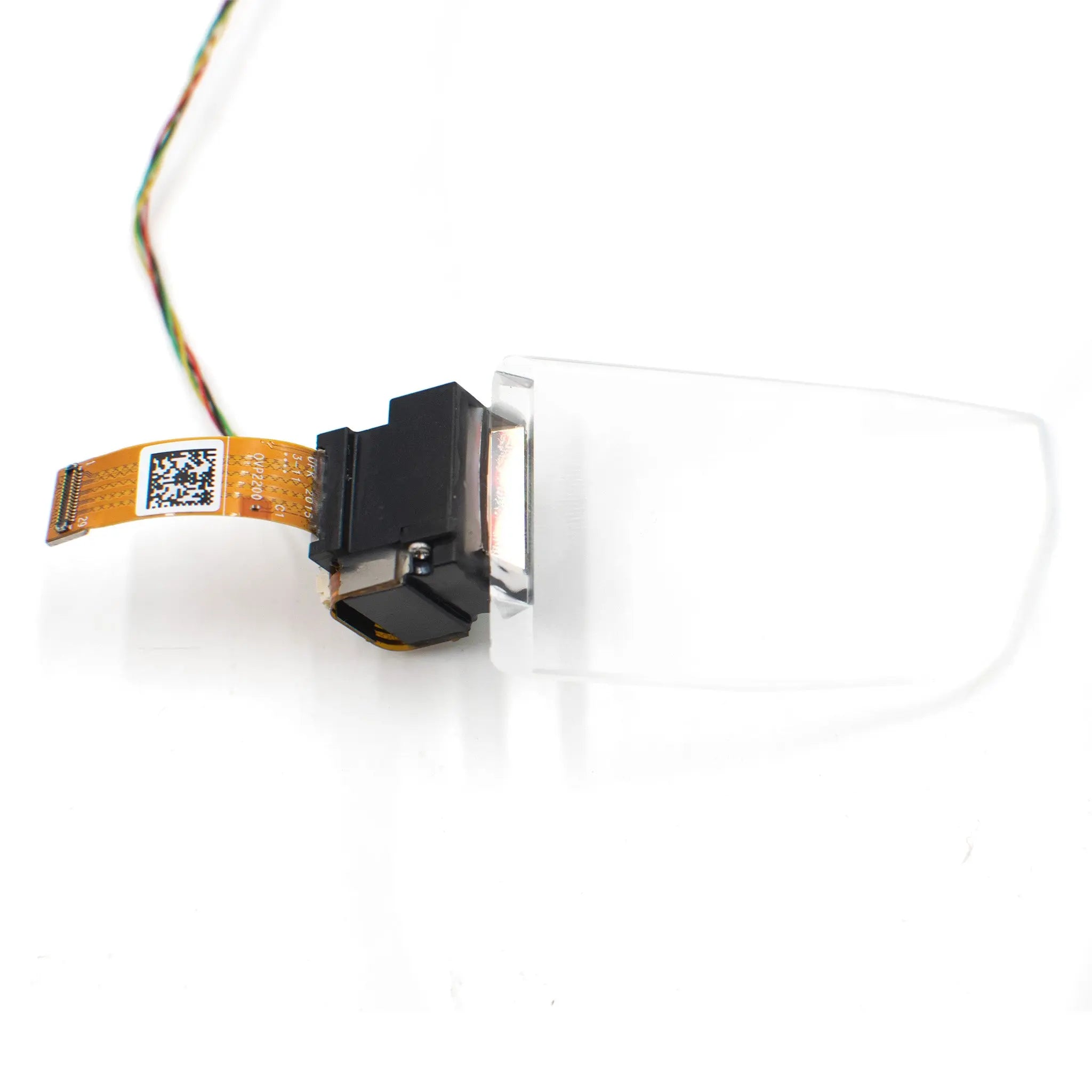
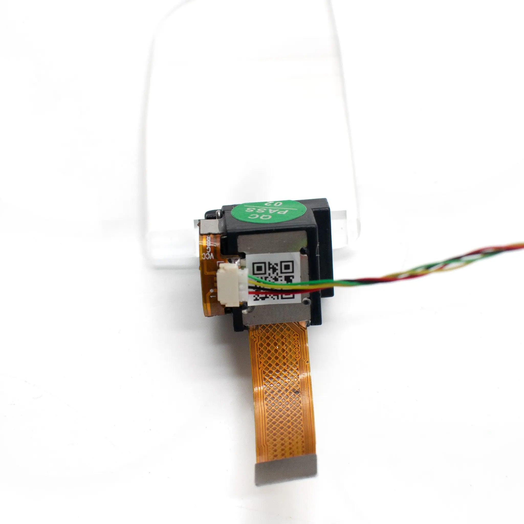
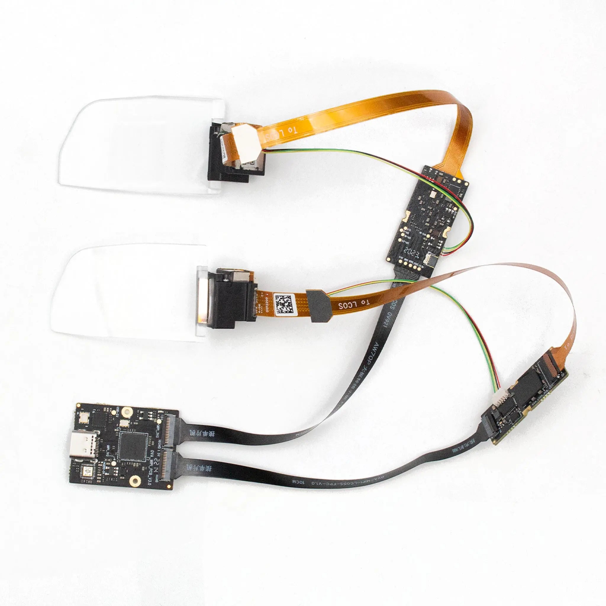
AR Optical Waveguide Module 1280x720
Advanced waveguide technology delivering high-performance AR visuals with 30° field of view and 1280×720 resolution. Features full-color RGB display, 800 nits brightness, and optically infinite imaging for seamless digital-physical integration.
Engineered for augmented reality applications, this waveguide module provides exceptional 500:1 contrast ratio with over 80% brightness uniformity. The 8-bit grayscale ensures detailed visuals while the 10×10mm eye movement range offers comfortable viewing flexibility.
- Immersive Imaging: Optically infinite imaging distance creates natural depth perception
- Color Accuracy: Full-color RGB reproduction for vibrant digital overlays
- Lightweight Design: Thin transparent waveguide layers enable sleek AR eyewear integration
| Parameter | Specification |
|---|---|
| Field of View | 30°=26.16°(H)×14.71°(V) |
| Resolution | 1280 × 720 |
| Color | Full-color RGB |
| Brightness | 800 nits |
| Contrast Ratio | 500:1 (FOFO) |
| Brightness Uniformity | Over 80% |
| Grayscale | 8-bit |
| Eye Movement Range | 10×10 mm |
| Transmittance | 85% |
| Imaging Distance | 55 inch@ 3M |
Customize AR display modules for specialized applications with our flexible manufacturing capabilities.
- Optical Customization: Birdbath or waveguide solutions tailored to your FOV and brightness requirements
- Display Options: Micro OLED or Micro LED modules in color/monochrome with ultra-high brightness/resolution
- Adapter Design: Custom interfaces, miniaturization, low power consumption solutions
- Bulk Procurement: Volume discounts for OEM/ODM partnerships
Surgical navigation and medical training with real-time data overlay
Equipment diagnostics and repair guidance in field operations
Tactical information display in simulated combat environments
Seamlessly integrates with binocular AR glasses featuring birdbath optical systems. Our custom adapter solutions ensure compatibility with various display interfaces.
- Optical Integration: Designed for binocular AR glasses with birdbath optical modules
- Adapter Support: Custom interfaces for miniaturization and low power consumption
Documentation: Access detailed specifications and integration guides
Download Product Datasheet
3D Model Files
Adapter Design Files