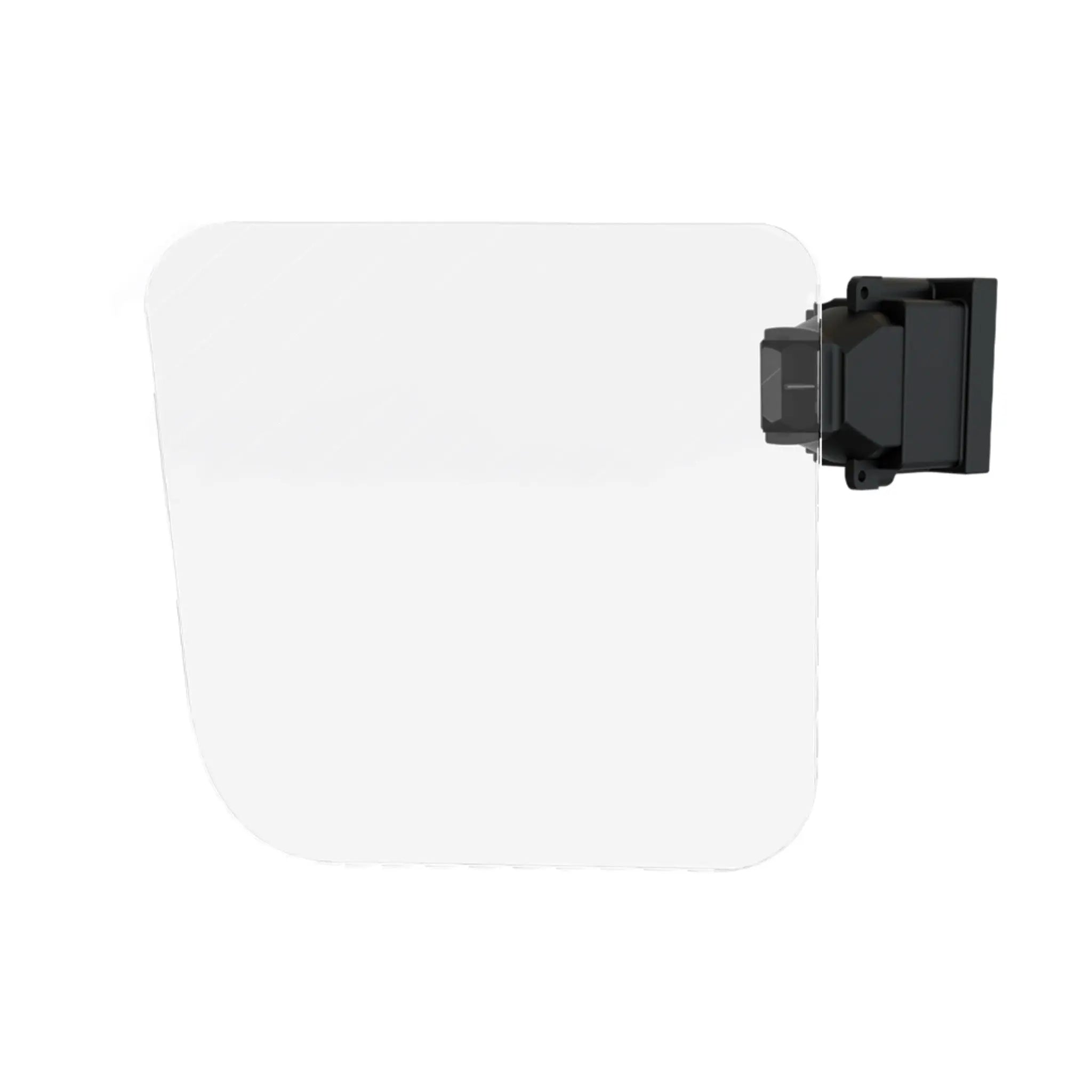
AR Optical Waveguide Module 1920x1080
- 💹 Enjoy a 20% discount for orders over 500
- 📉 A 15% discount is available for orders ranging from 200 to 499
- 🎁 A 10% discount is available for orders ranging from 50 to 199
- 🎁 A 5% discount is available when ordering 10-49
Order samples, immediate delivery.
Factory bulk lead time: 3 weeks.
Interested in customizing this product? Get in touch with us.


AR Optical Waveguide Module 1920x1080
- 💹 Enjoy a 20% discount for orders over 500
- 📉 A 15% discount is available for orders ranging from 200 to 499
- 🎁 A 10% discount is available for orders ranging from 50 to 199
- 🎁 A 5% discount is available when ordering 10-49
AR Optical Waveguide Module 1920x1080
Our AR Optical Waveguide Module delivers an immersive augmented reality experience with its advanced waveguide technology. Featuring a wide 60° field of view and full-color RGB display, this module provides crisp, vibrant visuals while maintaining a compact form factor ideal for AR glasses and wearable devices.
The waveguide module utilizes LCOS technology with precise optical engineering to deliver optically infinite imaging distance, reducing eye strain during extended use. With an 8-bit grayscale and over 90% brightness uniformity, the display ensures consistent image quality across the entire visual field.
- Advanced Waveguide Technology: Thin transparent layers bend and reflect light to project virtual images with minimal bulk.
- High Contrast Ratio: 500:1 (FOFO) contrast ensures sharp image quality in various lighting conditions.
- Wide Eye Movement Range: 12×8mm eye box provides comfortable viewing with flexibility in positioning.
- Compact Design: Only 4.4CC displacement volume enables integration into sleek AR eyewear designs.
| Optical Parameter | Specification |
|---|---|
| Field of View | 60°=52.3°(H)×29.4°(V) |
| Resolution | 1920 × 1080 |
| Color | Full-color RGB |
| Brightness | 500 nits |
| Contrast Ratio | 500:1 (FOFO) |
| Brightness Uniformity | Over 90% |
| Grayscale | 8-bit |
| Eye Movement Range | 12×8mm |
| Transmittance | 85% |
| Imaging Distance | Optically Infinite |
| Displacement Volume | 4.4CC |
We offer customized AR display solutions for businesses seeking to integrate advanced waveguide technology into their products. Our engineering team works closely with clients to develop tailored solutions that meet specific application requirements.
- Custom Optical Modules: Tailored waveguide designs with specific FOV, brightness, and form factor requirements.
- Binocular Configurations: Symmetrically designed left and right modules with 63.5mm display center distance optimized for human pupil spacing.
- Bulk Procurement Programs: Volume discounts and customized configurations for enterprise deployments.
- Technical Support: Comprehensive engineering support from prototyping to mass production.
Lightweight, high-performance display modules for enterprise AR glasses used in logistics, manufacturing, and field service applications.
Surgical guidance systems and medical training simulations requiring precise, high-contrast overlays on real-world views.
Next-generation wearable displays for gaming, multimedia, and everyday augmented reality experiences.
Compatibility Information: The module features a 30-pin FPC connector compatible with HIROSE BM23FR0.6-30DS-0.35V(51) connectors. LED connector specification: 1mm High, 0.5mm Pitch, 4-Pin (Model: AYF530435).
Operating Conditions: Recommended use at 10°C to 50°C with 45% to 70% RH. Tested for extreme conditions including operation at 0°C to 60°C and storage at -10°C to 70°C.
Technical Notes: The theoretical service life exceeds 12,000 hours under standard operating conditions (10 mW/mm²). All samples passed 240 hours of continuous operation aging tests with no display abnormalities or flickering observed.
Resources: Download Datasheet | 3D Model Files

