


Principle of Diffractive waveguide
Diffractive Grating
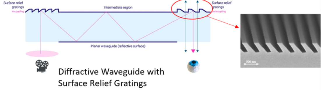
In order for the virtual image generated by the optical machine to be transmitted to the human eye by the optical waveguide, there needs to be a process of “couple-in “and “couple-out “of the waveguide. In the geometric optical waveguide, these two processes are completed by traditional optical components such as prisms and "semi-transparent and semi-reflective" mirror arrays. The process is simple and easy to understand. However, there are challenges in volume and mass production process. In Diffractive waveguides, the traditional optical structure is replaced by a Diffractive Grating. Its generation and popularity benefit from the technological advancement trend of optical elements from millimeter level to micro/nano level, from "stereo" to "planar".
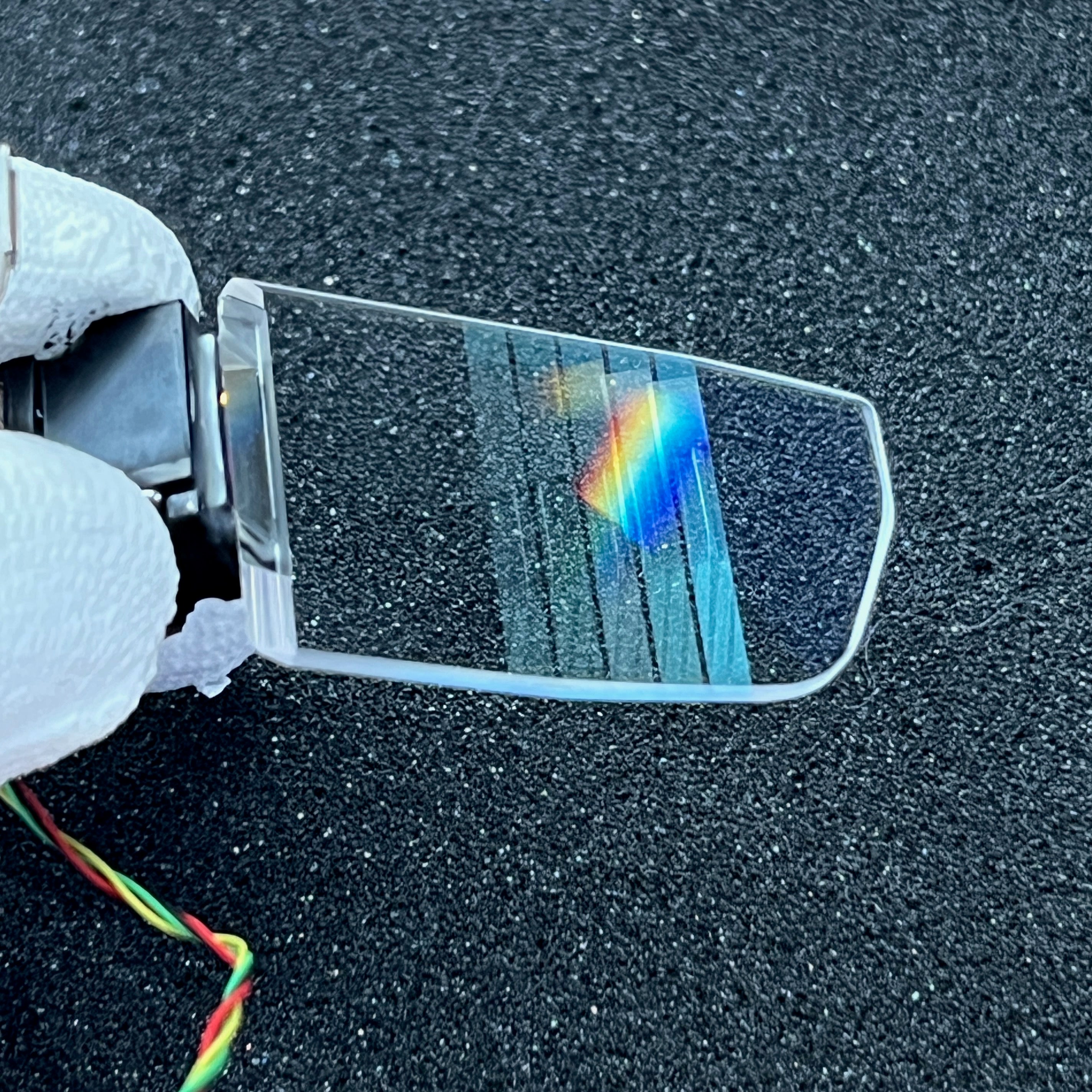
In simple terms, it is an optical element with a periodic structure, which can be peaks and valleys embossed from the surface of the material.

It can also be the "light and dark interference fringe" formed by holographic technology in the internal exposure of the material, but in the final analysis, it causes a periodic change of the refractive index n (refractive index) in the material.

This period is typically on the order of micro - and nanometer, on the order of the wavelength of visible light (~450-700nm), to allow effective manipulation of light.
The "light splitting" of the diffractive **** grating is reflected in two dimensions, as shown below. Assuming that the incident light is a single wavelength of green light, it will be divided into several diffraction orders by the diffractive **** grating, and each diffraction order will continue to propagate along different directions, including the reflection diffraction (R0, R±1, R±2,...). And transmission diffraction (T0, T±1, T±2,...) The diffraction Angle of each diffraction order (θm, m=±1, ±2,...) Determined by the incident Angle of light (θ) and the period of the grating (Λ), the diffraction efficiency of a certain diffraction order (that is, a certain direction) can be optimized to the highest by designing other parameters of the grating (material refractive index n, grating shape, thickness, duty cycle, etc.), so that most of the light mainly propagates along this direction after diffraction.

On the basis of dividing the incident light into different diffraction orders, another "light splitting" dimension of diffraction gratings is reflected in dispersion, that is, for the same grating period, the diffraction angles (θm) of different wavelengths are also different. As shown above, assuming that the incident light is white light, the longer the wavelength of the light diffraction Angle is larger, that is, the diffraction Angle of the figure is red light (R)> Green light (G)> Blue light (B), this dispersive effect is reflected in both reflection and transmission diffraction.
Principle
1D-EPE
One can simply use an incoming grating to couple light into the waveguide, and then replace the specular array with an outgoing grating. That is, the total reflection light "walks" in the waveguide like a snake. When it meets the grating on the surface of the glass substrate, a part of the light is released into the eye through diffraction, and the rest of the light continues to spread in the waveguide until the next time it hits the grating on the surface of the waveguide.

2D-EPE
- SRG
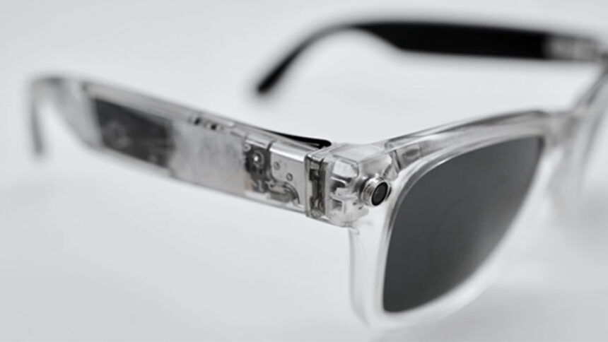
The grating structure can manipulate the characteristics of light in a greater degree of freedom than traditional optical devices, and also realize pupil expansion in the other direction (that is, along the Y direction of the nose bridge), which not only makes AR glasses able to accept a wider range of pupil distance, but also makes it more compatible with people with different face shapes and nose heights.

- VHG
A similar three-region grating arrangement is also used for VHG to achieve 2-D pupil dilation. You can see that when the input grating couples light into the waveguide, it will enter a fold/turn grating region. In this region, the grating gully direction is at a certain Angle from the incident grating. Let's assume it is 45 degrees for the sake of understanding. So it acts like a 45 degree mirror and it reflects the light from the X direction to the Y direction.
And in the process of this turning, because the total reflection traveling light will meet the turning grating several times, each time a part of the light will be turned 90 degrees, and the other part of the light will continue to advance laterally, which realizes the one-dimensional pupil enlargement in the X direction similar to 1D-EPE, but the light after pupil enlargement does not couple out of the waveguide. Instead, it continues in the Y direction into the third grating region, the output grating.
The structure of the outgoing grating is similar to that of the incoming grating, but the area is much larger and the direction of the grating gully is perpendicular to that of the incoming grating, because it is responsible for pupil dilation in the Y direction. The process is similar to that in 1D-EPE, except that it receives multiple beams instead of one. We assume that the incident light of a single pupil is expanded into M x 1 pupils (i.e., a one-dimensional array in the X direction) after passing through the turning grating, and then it is expanded into a two-dimensional matrix M x N after passing through the exit grating, where N is the number of total reflections of the light in the exit grating area, that is, the number of dilated pupils.
2D-Grating
That is, the grating has periods in at least two directions, and more intuitively, the unidirectional "gullies" become columnar arrays.
As shown below, the light coupled into the waveguide from the incident grating (region 1) directly enters region 3. The two-dimensional cylindrical array in this region can simultaneously expand the beam in both X and Y directions, and while propagating, part of the light is coupled out and enters the human eye.

Read more
In the world of Augmented Reality (AR), the performance and quality of optical modules significantly impact user experience. Thus, today, we delve into the DM-ARM-101 AR optical module, a highly s...
According to a recent report from The Information, Meta has ambitious plans to launch its first Augmented Reality (AR) glasses in 2024. These cutting-edge glasses, codenamed "Orion" within Meta, wi...
Leave a comment
This site is protected by hCaptcha and the hCaptcha Privacy Policy and Terms of Service apply.