


What is LCD means?
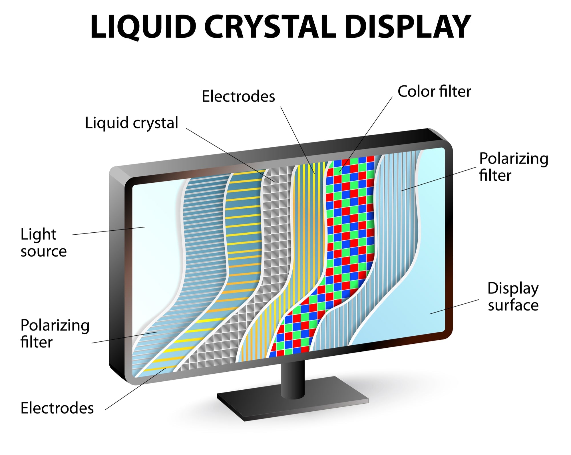
LCD means Liquid Crystal Display, using liquid crystals sandwiched between polarized glass to modulate backlight, creating images. Common in TVs/phones, IPS panels (e.g., iPad Pro) offer 178° viewing angles, while TN panels respond faster (~5ms), balancing color accuracy and speed for daily use.
The Need for Light
The efficiency of this system is critical, as the backlight can account for up to 80% of a display's total power consumption, directly impacting battery life in portable devices which can see a variance of 5 to 20 hours of usage based on its brightness setting. The industry standard for modern LCD backlights is the LED (Light Emitting Diode) array, which has largely replaced older CCFL (Cold Cathode Fluorescent Lamp) technology due to its superior energy efficiency, longer lifespan exceeding 50,000 hours, and slimmer profile, enabling panels with a thickness of just a few millimeters.
The core components of a modern LED backlight system work in concert to create this essential foundation of light.
-
The LED Light Source: LEDs are the workhorses. A typical LCD TV backlight might use hundreds to over a thousand individual white LEDs arranged in an array behind the panel. The quality of white light is crucial; it's engineered to have a high Color Rendering Index (CRI) of over 90% and a specific correlated color temperature (CCT), often around 6500 Kelvin (K), to ensure it can be filtered into accurate colors later. Their light output is measured in nits (candelas per square meter), with consumer monitors typically ranging from 200 to 1500 nits of peak brightness.
-
The Light Guide Plate (LGP): In edge-lit displays—common in thinner monitors and laptops—the LEDs are placed along the sides. The LGP, a flat plate of optical-grade plastic like PMMA (acrylic) with a refractive index of approximately 1.49, then captures this light. Using principles of total internal reflection, it scatters the light uniformly across its surface through a precisely printed pattern of microscopic dots. The density and size of these dots, which can vary from 10 to 500 micrometers, are calculated to ensure brightness uniformity of over 85% across the entire screen area, preventing bright spots or dark corners.
-
Diffusers and Reflectors: Once light exits the LGP, it passes through one or more diffuser sheets. These sheets, often made of polyester or polycarbonate with a thickness of only 0.1 to 0.5 mm, contain microscopic particles that scramble the light's direction, smoothing out any remaining minor inconsistencies to achieve a uniformity rate exceeding 90%. Any light that travels backward away from the screen is captured by a reflective sheet placed underneath the LGP, bouncing it back toward the viewer. This recycling of light can improve the overall optical efficiency of the backlight system by 15% to 30%, directly reducing the power required.
-
Brightness Enhancement Films (BEFs): These are perhaps the most clever components. BEFs are thin plastic sheets covered with a structured array of microscopic prisms. These prisms, with precise angles often around 90 degrees, focus light that is traveling at wide angles into a tighter viewing cone perpendicular to the screen. This recycling and focusing process can effectively double the on-axis brightness perceived by the user, increasing luminance by 60% to 100% without adding a single extra LED, thus optimizing the luminaire efficacy (lm/W) and controlling the Bill of Materials (BOM) cost.
Taming Light's Direction
Trying to control this light with liquid crystals would be like trying to steer a car with a steering wheel that has 360 degrees of free play; you'd have no precise control. The solution is a component called the polarizer, a thin film that acts as a microscopic slatted fence. This first polarizer, often called the rear polarizer or input polarizer, is the gatekeeper. It has a defined transmission axis, and it only allows light waves vibrating parallel to this axis to pass through. This single step immediately blocks approximately 50% of the incoming light, but the resulting beam is now orderly, with all its light waves oscillating in a single, unified direction.
The most common type used in LCDs is a linear polarizer, typically constructed from a 25 to 35 micrometer thick layer of polyvinyl alcohol (PVA) that is stretched to align its long-chain polymer molecules.This entire assembly is then laminated between two protective 50 to 100 micrometer thick tri-acetate cellulose (TAC) films to provide mechanical stability and environmental protection, resulting in a total polarizer thickness of around 0.2 millimeters.
The performance of a polarizer is measured by its single transmittance (how much natural light it lets through) and its polarization efficiency. A high-quality polarizer for an LCD will have a single transmittance of about 42% to 45% and an exceptionally high polarization efficiency of 99.95% or better, meaning less than 0.05% of "wrongly" aligned light leaks through to disrupt the image.
In a standard Twisted Nematic (TN) or In-Plane Switching (IPS) panel, the rear polarizer is set to a 0-degree orientation. The light that emerges is now perfectly prepared for the next stage: interaction with the liquid crystal layer. The liquid crystals' primary function is to precisely rotate the polarization direction of this prepared light by a specific amount, typically up to 90 degrees, based on the applied voltage.
The Liquid Crystal Layer
The liquid crystal material itself is not a single substance but a precisely formulated mixture of 10 to 20 different organic compounds, each chosen for specific electro-optical properties like rotational elasticity, viscosity, and dielectric anisotropy. The primary function of this layer is to act as a voltage-controlled light valve. When no voltage is applied, the rod-like liquid crystal molecules naturally twist by 90 degrees from one glass substrate to the other, carefully guiding the polarization of the incoming light. Applying an electric field—typically ranging from 1 to 5 volts—causes the molecules to untwist and align with the field, changing their ability to guide the light.
The entire structure is contained between two ultra-thin glass substrates, each about 0.3 to 0.5 millimeters thick. The inner surfaces of these glass plates are coated with a transparent conductive layer, Indium Tin Oxide (ITO), which has a light transmittance of over 90%. This ITO layer is etched into a grid of microscopic electrodes that define the screen's pixels. For a standard Full HD (1920x1080) display, this grid consists of over 2 million individual pixel electrodes and their corresponding thin-film transistors (TFTs). The alignment of the liquid crystals is initiated by polyimide alignment layers rubbed onto the ITO surface with a precision of less than 0.5 degrees of angular error, ensuring the initial molecular twist is uniform across the entire >95% of the active screen area.
|
|
|
|
|
|---|---|---|---|
|
|
|
|
|
|
|
|
|
|
|
|
|
|
|
|
|
|
|
|
|
|
|
|
|
A critical parameter is the threshold voltage (Vth), usually around 1.5 to 2.5 volts, below which the crystals begin to twist and let light pass. The saturation voltage (Vsat), typically 4 to 5 volts, is where maximum molecular alignment is achieved, blocking the most light. The response time, a combination of the rise time (on) and fall time (off), is heavily influenced by the LC mixture's rotational viscosity and the cell gap.
While rise time can be fast (e.g., 1-3 ms) due to the driving voltage, the fall time (e.g., 5-15 ms) relies on the natural elastic recovery of the crystals, a key limitation in fast-moving content. The operating temperature range is also crucial; LC materials are formulated to perform consistently from -30°C to 80°C, outside of which response times can slow by over 50% or the layer may even freeze.
Creating the Picture
The magic of an LCD happens in the precise collaboration between the liquid crystal layer and the second polarizer, often called the analyzer. This final polarizer is the ultimate gatekeeper, strategically positioned at a 90-degree angle to the first one. Its sole purpose is to either block or allow light to pass based on the manipulations performed by the liquid crystals. When the liquid crystals are in their natural, twisted state, they rotate the polarization of the incoming light by exactly 90 degrees.
By applying a voltage between the threshold voltage (~1.5V) and the saturation voltage (~5V), the liquid crystal molecules can be made to untwist to an intermediate angle—for example, 22.5, 45, or 67.5 degrees. At a 45-degree twist, only a portion of the light's polarization is rotated correctly to pass through the second polarizer. This results in a specific percentage of light transmission, creating a shade of gray.
Modern displays control this with incredible precision using 8-bit to 10-bit drivers, allowing for 256 to 1024 distinct voltage levels per sub-pixel, which translates directly into 256 or 1024 shades of gray for red, green, and blue independently. The response time for a full grayscale-to-grayscale (GtG) transition is a critical performance metric, varying from 1 millisecond on high-end gaming monitors to 20 milliseconds on slower, cheaper panels, directly impacting motion blur. The voltage applied to each sub-pixel is refreshed 60 to 240 times per second (the refresh rate) to maintain a stable image.
|
|
|
|
|---|---|---|
|
|
|
|
|
|
|
|
|
|
|
|
|
|
|
|
|
|
|
|
|
|
|
|
Each of the over 2 million pixels on a Full HD screen has its own dedicated transistor, which acts as a tiny, fast switch. This design allows each pixel to maintain its charge and state for the entire frame duration of ~16.7 milliseconds (at 60Hz), eliminating the crosstalk and ghosting that plagued older passive-matrix displays.
How Colors Are Made
A subpixel with a red filter, for instance, absorbs most of the green and blue wavelengths, transmitting only the red portion of the original white light, with a typical transmittance efficiency of only 25-30% for that color band. The final color you perceive is a result of your brain blending the intensity of light from these three tiny, tightly packed subpixels, which can have a density exceeding 500 pixels per inch (ppi) on a high-end smartphone display.
The engineering behind color reproduction is a complex balance of material science, optical physics, and electronic control. Here’s a breakdown of the key elements:
-
The Color Filter Array (CFA): The filters are made from pigment-dispersed resins with high thermal stability (up to >200°C) to withstand manufacturing processes. The performance of a color filter is measured by its color gamut, which defines the range of colors it can produce. A standard sRGB gamut covers about 70-80% of the visible color space, while wider gamuts like DCI-P3 target >90% coverage.
-
The Subpixel Structure: The physical size of each subpixel is minuscule; on a 27-inch 4K monitor (3840x2160 pixels), each subpixel measures roughly 75 micrometers wide.
-
Additive Color Mixing: By controlling the intensity of red, green, and blue light with 8-bit precision (256 intensity levels each), the display can produce 256 x 256 x 256 = 16.7 million possible color combinations. A color like yellow is created by turning the red and green subpixels to near full intensity (~100%), while the blue subpixel is turned completely off (0%). A pale lavender might be a mix of red at 80%, blue at 90%, and green at 60%.
Bringing It All Together
A functional LCD panel is a marvel of integration, where up to 15 or more distinct layers are assembled with microscopic precision to create a single, coherent imaging system. The journey from a digital signal to a visible pixel involves a tightly synchronized sequence of events that occurs in a timeframe of milliseconds, coordinated by a central timing controller (TCON) chip.
The overall optical efficiency of this entire stack is remarkably low, typically only 5% to 8%, meaning over 90% of the light generated by the backlight is absorbed or lost throughout the assembly. This integration process happens on an immense scale; a Gen 10.5 production line can process glass substrates larger than 3 meters by 3 meters, which are later cut into multiple 55-inch to 85-inch TV panels, with a total cycle time of several days from start to finish.
The assembly and synchronization process can be broken down into a critical path of interdependent systems. The journey of a single frame of image data, say a 1920x1080 resolution frame refreshing 60 times per second, follows a precise pathway:
-
Signal Input and Processing: A digital signal (e.g., HDMI or DisplayPort) carrying the 24-bit color information for 2,073,600 pixels arrives at the display's main board. The TCON chip receives this data and, using a clock signal with a frequency of >150 MHz, begins processing.
-
Row-by-Row Activation: The TCON does not address all 2 million+ pixels at once. Instead, it uses a sequential scanning method. It activates the thin-film transistor (TFT) switches for the first row of pixels by sending a gate pulse down the first gate line. This opens the transistors for all pixels in that row for a brief period of about 20 microseconds. Simultaneously, the source driver ICs, which are high-speed digital-to-analog converters, send the precise analog voltages (from 0 to 5V) for each of the 3840 subpixels in that row (3 per pixel for Full HD) down the source lines.
-
The Integrated Optical Path: As this electronic addressing happens, the integrated optical stack works in parallel. The backlight, consuming 60-80% of the total system power, emits white light with a uniformity of over 85%. This light is first polarized, losing ~50% of its intensity immediately. It then passes through the liquid crystal layer, where the localized voltage in each subpixel cell, only 3-4 micrometers thick, twists the light by a specific angle between 0 and 90 degrees. This "gated" light then hits the color filters, where another 70-75% of the remaining light is absorbed by the pigments, leaving only the intended red, green, or blue component.
The response time, critical for a 1ms GtG gaming monitor, is a function of the liquid crystal material's viscosity and the driving voltage strength. Every component, from the glass with a thickness of 0.5mm to the polarizers with a tolerance of ±0.1 degrees in alignment, must perform to its specified parameters for the entire system to produce the sharp, bright, and colorful image we take for granted.
Read more
In this article, we try to organize the kinds of display interfaces, and how they differ from each other. There is the outline. Display Interface Display interface and protocol External Interface...
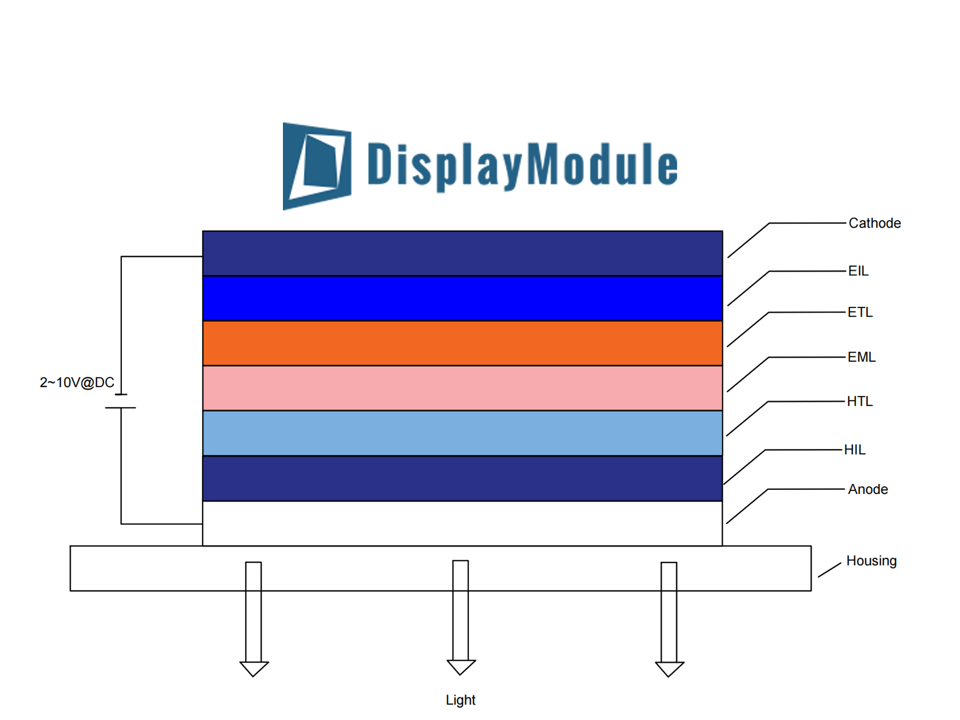
OLEDs emit light via organic films (100–200nm thick) sandwiched between anode/cathode. Electrons/holes inject, merge in emissive layer, exciting molecules to release photons (100% NTSC color). No b...
Leave a comment
This site is protected by hCaptcha and the hCaptcha Privacy Policy and Terms of Service apply.