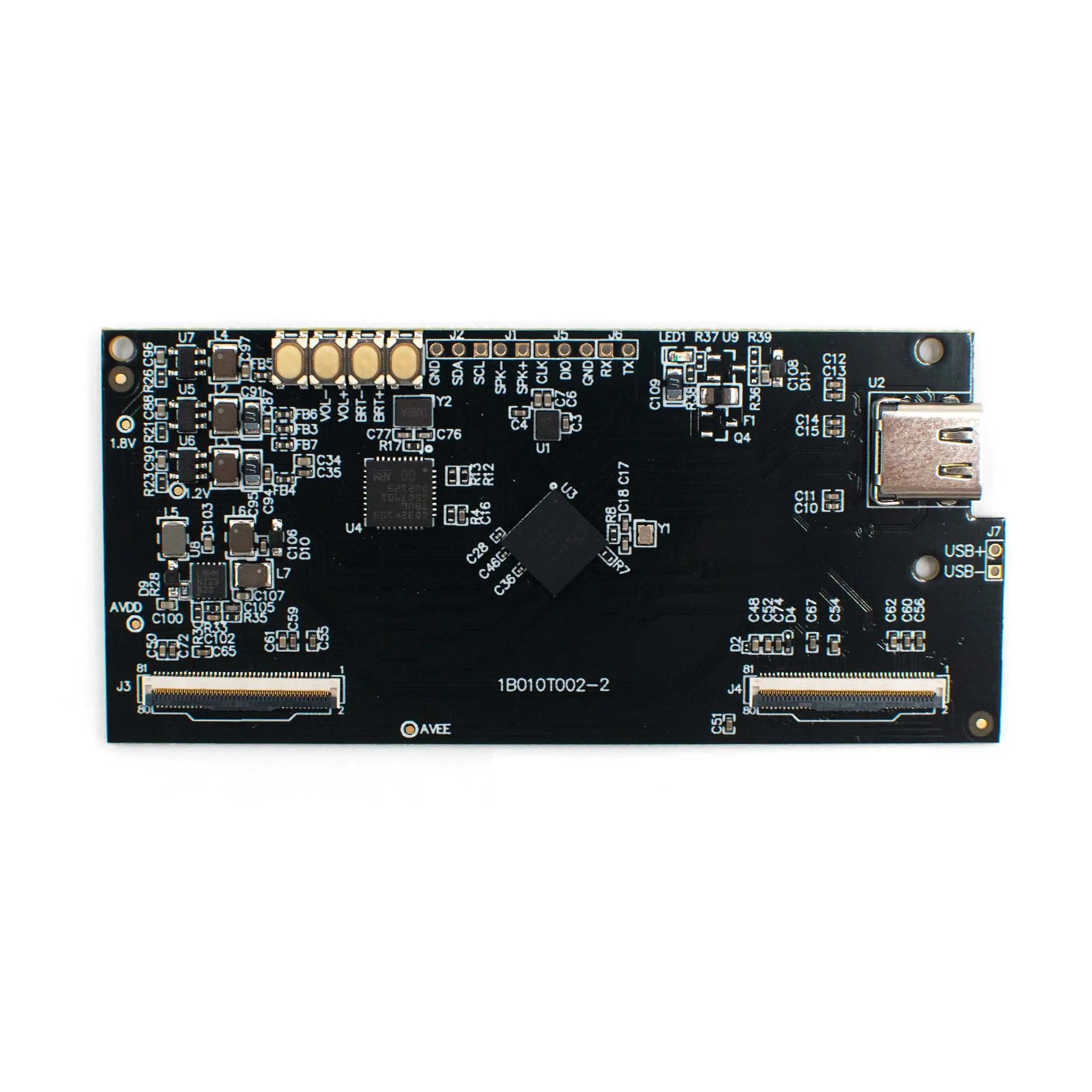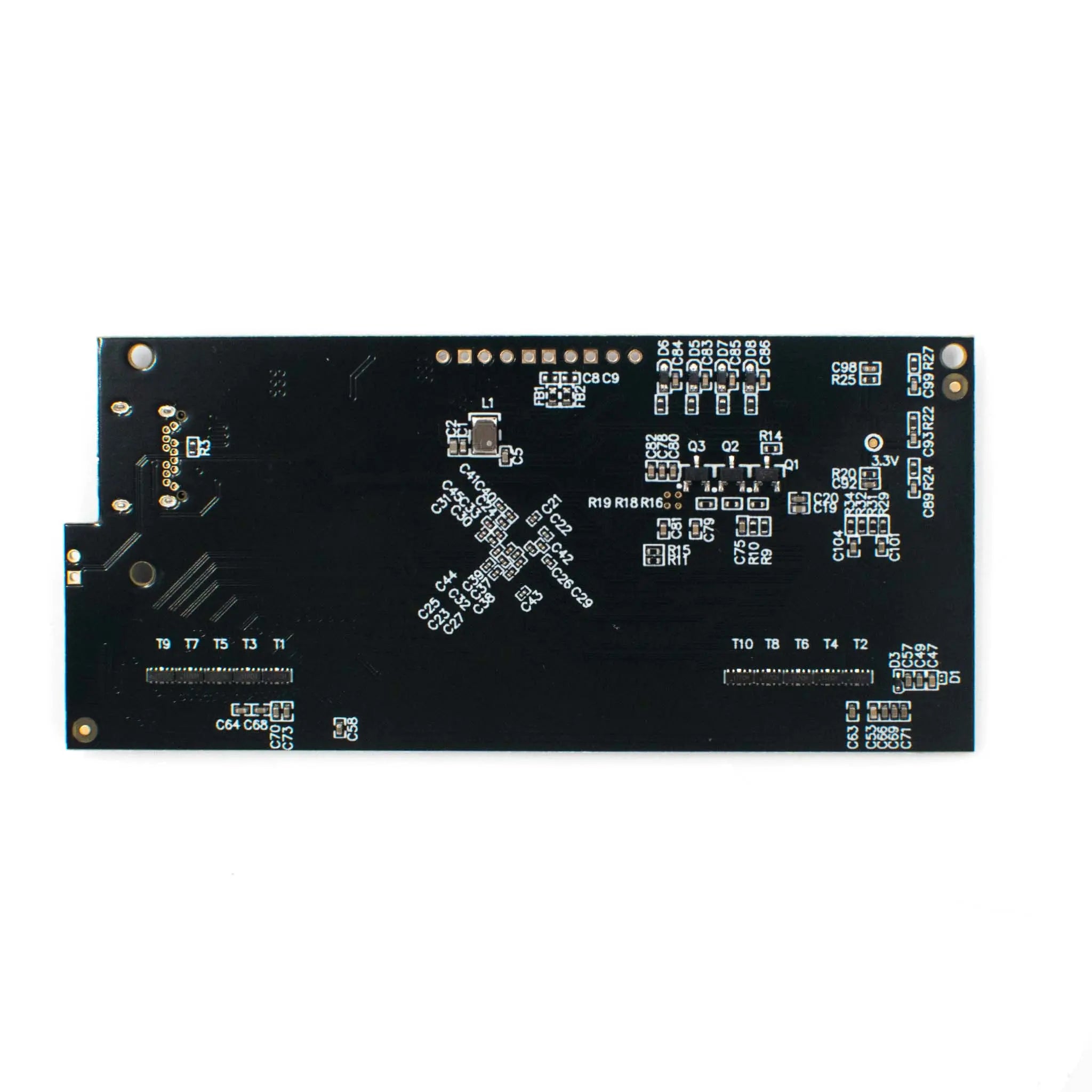

Type-C to MIPI Adapter for Micro OLED
- 💹 Enjoy a 20% discount for orders over 500
- 📉 A 15% discount is available for orders ranging from 200 to 499
- 🎁 A 10% discount is available for orders ranging from 50 to 199
- 🎁 A 5% discount is available when ordering 10-49
Interested in customizing this product? Get in touch with us.
Order samples, immediate delivery.
Factory bulk lead time: 3 weeks.


Type-C to MIPI Adapter for Micro OLED
- 💹 Enjoy a 20% discount for orders over 500
- 📉 A 15% discount is available for orders ranging from 200 to 499
- 🎁 A 10% discount is available for orders ranging from 50 to 199
- 🎁 A 5% discount is available when ordering 10-49
Dimensions

Type-C to MIPI Adapter for Micro OLED
This advanced Type-C to MIPI adapter enables plug-and-play functionality for Micro OLED displays when flashing different firmware versions. It seamlessly connects video output devices through Type-C cables to achieve screen mirroring effects, ideal for silicon OLED testing, demo presentations, and VR/AR product development.
Designed with a GD32F103TBU6 32-bit MCU and LT7911B bridge chip, this adapter provides precise control over display parameters and supports firmware updates via USB. The compact form factor makes it ideal for integration into portable devices and embedded systems.
- Plug-and-Play Functionality: Works with different firmware versions without additional configuration
- Real-time Adjustments: Control volume and brightness through physical buttons or software commands
- 2D/3D Switching: Seamlessly transition between display modes via button press or command
- Firmware Update Capability: Update both MCU and LT7911B firmware through USB interface
- Multi-System Compatibility: Supports Windows, Linux, Android and other operating systems
| Parameter | Specification |
|---|---|
| Core Architecture | GD32F103TBU6 MCU + LT7911B Bridge Chip |
| Input Interface | Type-C with DP ALT Mode |
| Output Interface | MIPI DSI |
| Supported Display Sizes | 0.49", 0.50", 1.03" Micro OLED |
| Max Resolution (2D Mode) | Up to 2560×2560@60Hz |
| Max Resolution (3D Mode) | Up to 3840×1920@75Hz |
| Control Interface | 4-button configuration (VOL±, BRT±) |
| Audio Support | 1W/8Ω speaker (max 2W/4Ω) |
| Operating Systems | Windows, Linux, Android, ChromeOS |
| Environmental Rating | Wide temperature & voltage operation |
We offer customized adapter solutions for businesses requiring specialized configurations or bulk orders:
- Custom Interface Configurations: Tailored input/output interfaces including HDMI, DisplayPort, DVI, and VGA
- Specialized Form Factors: Miniaturized designs for portable devices or specific industrial enclosures
- Brand Customization: Custom shells with company branding, colors, and logos
- Bulk Order Programs: Volume discounts for OEMs and system integrators
- Extended Temperature Support: Industrial-grade operation from -40°C to 85°C
Essential tool for developing binocular VR/AR products using silicon-based solutions with Type-C video transmission
Critical for silicon OLED quality verification and performance validation during manufacturing
Enables high-quality display presentations for sales demonstrations and trade shows
Compact solution for portable medical devices, industrial HMDs, and field equipment
Documentation: Comprehensive datasheets and user manuals available for download:
This adapter works seamlessly with the following Micro OLED displays:
| Adapter Type | Compatible Display | Display Specifications |
|---|---|---|
| 0.49" Micro Display | DM-OLED049-1002 | 1920×1080@90Hz, 1800nits |
| 0.49" Mono Micro Display | DM-OLED049-1004 | 1920×1080@90Hz, 20,000nits |
| 0.50" Micro Display | DM-OLED050-1005 | 1600×1200@120Hz, 1000nits |
| 1.03" Micro Display | DM-OLED103-1010 | 2560×2560@120Hz, 1000nits |

